Example of shear force and bending moment diagram, Mechanical Engineering

Assignment Help:

Example of Shear force and bending moment diagram:

Q: Draw the Shear Force and bending moment diagram for the simply supported beam loaded as shown in the figure given below. 


104_Example of Shear force and bending moment diagram1.png

1080_Example of Shear force and bending moment diagram.png

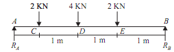
Sol.: Let reaction at support A and B be, RA  and RB  First find support reaction

For that,

1873_Example of Shear force and bending moment diagram2.png

Taking moment about the point A,
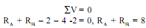
ΣMA = 0

2 X 1 + 4 X 2 + 2 X 3 - RB  X 4 = 0

RB = 4KN                                                                                           ...(2)

From equation (1), RA  = 4KN                                                                                                                       ...(3)

Calculation for Shear force Diagram

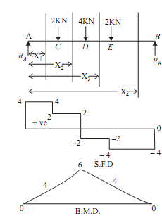
Draw the section line, here total four section line, which break the load RA and 2KN(Between A and C),

2KN and 4KN(Between C and D),

4KN and 2KN (Between D and E) and

2KN and RB(Between E and B) Consider left portion of beam Take section 1-1

Force on left of section 1-1 is RA

SF1-1 = 4KN (constant value)

Constant value means value of shear force at both the nearest point of section is equal that is

SFA = SFC  = 4KN                                                                               ...(4)

Take section 2-2

Forces on left of section 2-2 is RA  and 2KN

SF2-2 = 4 - 2 = 2KN (constant value)

Constant value means value of shear force at both the nearest point of section is equal that is

SFC = SFD  = 2KN                                                                                                                        ...(5)

Take section 3-3

Forces on left of section 3-3 is RA, 2KN, 4KN

SF3-3 = 4 - 2 - 4 = -2KN (constant value)

The constant value means that value of shear force at both the nearest point of the section is equal that is

SFD = SFE  = -2KN                                                                                                                      ...(6)

Take section 4-4

Forces on left of the section 4-4 is RA, 2KN, 4KN, 2KN

SF4-4 = 4 - 2 - 4 - 2 = - 4KN (constant value)

The constant value means that value of shear force at both the nearest point of section is equal that is

SFE = SFB  = -4KN                                                                                                                      ...(7)

Plot the SFD with the help of above shear force values.

Calculation for bending moment Diagram

Let

The distance of section 1-1 from A is X1

The distance of section 2-2 from A is X2

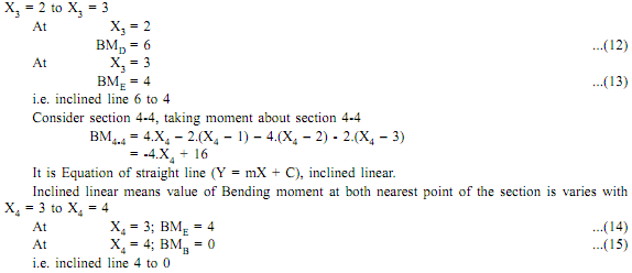
The distance of section 3-3 from A is X3

The distance of section 4-4 from A is X4

Take left portion of the beam

Take section 1-1, taking moment about section 1-1

BM1-1 = 4.X1

It is the Equation of straight line (Y = mX + C), inclined linear.

Inclined linear means that the value of bending moment at both the nearest point of section is varies with

1982_Example of Shear force and bending moment diagram3.png

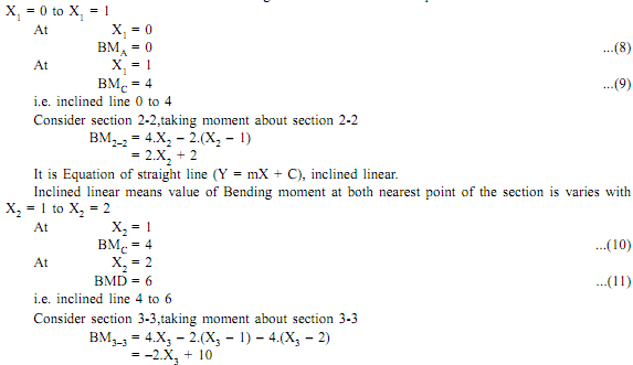
It is Equation of the straight line (Y = mX + C), inclined linear.

Inclined linear means that the value of bending moment at both the nearest point of section varies with

2107_Example of Shear force and bending moment diagram4.png

Plot the BMD with the help of obtained bending moment values.


Related Discussions:- Example of shear force and bending moment diagram

Short-term scheduling and control, Short-Term Scheduling And Control Th...

Short-Term Scheduling And Control The major objective at this stage is to make sure the efficient and smooth operation of the system in the event of unforeseen disturbances. Th

Dynamic movement in polar coordinates, You are required to investigate the ...

You are required to investigate the dynamic movement of a mass m sliding along a rod as shown in the diagram below. The rod is rotating at a constant angular velocity θ. The mass

Gantry crane, A gantry crane shown in figure above acts an auxiliary to...

A gantry crane shown in figure above acts an auxiliary to bridge cranes. It is provided with wheels and can be moved from open place to another as per requirements.

What are the approaches to the design of retaining walls, What are the appr...

What are the approaches to the design of retaining walls? The approach to the design of retaining walls can be started as follows: a. Chosse a trial dimension of the wall

Lets see, How is works watery flayer?

How is works watery flayer?

Objectives of general safety and service tips , Objectives After study...

Objectives After studying this general safety and services tips, you should be able to appreciate the importance of safety precautions, accomplish the servicing wo

Thermodynamics, Energy in state and it''s transition

Energy in state and it''s transitions

Maximum shear stress and angle of twist, Maximum shear stress and angle of ...

Maximum shear stress and angle of twist: Torques are applied on the shaft as illustrated in Figure. Discover in which portion of the shaft, maximum shear stress & angle of twi

Gears, What is the working depth of a gear

What is the working depth of a gear

Law of Parallelogram of Forces, To finding ? in Law of parallelogarm forces...

To finding ? in Law of parallelogarm forces We take Q sina(Along Vertical Side) & Q cosa(Along Horizontal Side) I didn''t get that point Q sina & Q cosa how it derived? Can you

Write Your Message!

Captcha
Free Assignment Quote

Assured A++ Grade

Get guaranteed satisfaction & time on delivery in every assignment order you paid with us! We ensure premium quality solution document along with free turntin report!

All rights reserved! Copyrights ©2019-2020 ExpertsMind IT Educational Pvt Ltd