Example of bars of varying cross section, Civil Engineering

Assignment Help:

Example of Bars of Varying Cross Section:

In the numerical example under consideration

δ = 750 × 300/( π/4) × 200 2 × 60 +750 × 400/(π/4) × 1352 × 60 + 750 × 200/(π/4) × 60 2 × 60 + 750 × 500/(π/4) × 100 2 × 60

+ 750/ (π/4) × 60 (300/2002+400/1352 + 200/602 + 500/1002) = 2.14865 mm

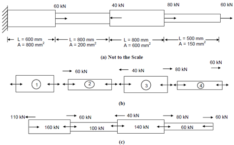
In the bar, display in Figure 16, the axial pull is applied at the ends and therefore the axial force in all the members is similar. On the bar, display in Figure 17(a), the external forces is applied at intermediate sections also. In such cases, the axial force in every member should be evaluated first, before any deformation calculations. This could be accomplished through considering equilibrium of each of the sections whereas external loads are applied. Though no external load has been prescribed at the LHS end, the support reaction has to be computed and taken as the external load. Equilibrium analysis could be simply carried out by treating each segment as a free body as display in Figure (b).

For instance, consider the equilibrium of the segment 4 in Figure (b). At the RHS end of the member a point load of 60 kN is applied. Therefore, for the member to be in equilibrium a force of - 60 kN should be applied at the RHS end of the member. Thus, the member is subjected to a tensile force of 60 kN which is represented through the internal arrows within accordance along with the sign conventions you have already learnt. Member 3 is pulled within a tensile force of 60 kN exerted through member 4 and further the external force of 80 kN also pulls the member in the similar direction, resulting in the member carrying a total tensile force of 140 kN. Proceeding therefore, the axial forces in all the members could be computed. To simplify the graphical representation we might display the member forces along along with external forces as shown in Figure(c).

Now let us compute the total elongation of the bar, taking the elastic modulus, E, as 200 kN/mm2.

2324_Example of Bars of Varying Cross Section.png

Figure

δ = ∑ δi = ∑  Pi Li /Ai Ei

=(160 × 600/800 × 200)+ (100 × 800/200 × 200)+ (140 × 800/600 × 200)+(60 × 500/150 × 200)

= 0.6 + 2.0 + 0.9333 + 1.0

= 4.53333 mm.


Related Discussions:- Example of bars of varying cross section

Moment distribution method hinges, Analyse the continuous beam using moment...

Analyse the continuous beam using moment distribution. A continuous beam ABCDE fixed at A carry a load of 2KN one metre from A at AB 3m. BC 3m, carry a UDL of 3KN/m and hinge at

Compute the negative skin friction of the pile group, A square pile group o...

A square pile group of 9 piles passes by a recently filled up material of 4.5 m depth. The diameter of the pile is 30 cm and pile spacing is 90 cm centre to centre. If the unconfin

Solid mensuration, Ask question #MiniThe base of an isosceles triangle and ...

Ask question #MiniThe base of an isosceles triangle and the altitude drawn from one of the congruent sides are equal to 18cm and 15cm, respectively. Find the lengths of the sides o

State the increase in earth pressure at rest, A wall with a smooth vertical...

A wall with a smooth vertical back and 9 metres high retains a moist cohesionless soil with a horizontal surface. The soil weighs 15 kN/m3 and has an angle of internal friction of

Unsealed contraction joints in concrete pavement, Unsealed contraction join...

Unsealed contraction joints in concrete pavement For unreinforced concrete pavement, contraction joint is an approximately 3mm wide groove with a depth of about one-third to o

Surveying, with a neat well labelled sketch, explain reciprocal ranging.

with a neat well labelled sketch, explain reciprocal ranging.

Yugty, #quesjjhjhhjtion..

#quesjjhjhhjtion..

Bridge loadings, Bridge Loadings: Loadings of bridges have been standa...

Bridge Loadings: Loadings of bridges have been standardized by the Roads Congress. The major features of the various load classes are given below : Bridges and culvert

Bond breaker for joint sealant, Joint sealant must be designed and construc...

Joint sealant must be designed and constructed to allow free extension and compression during the opening and closure of joints. In case joint sealants are attached to joint filler

Explain the well drawdown equations - ground water, Explain the Well Drawdo...

Explain the Well Drawdown Equations Watch the units, especially if you use log 10 or ln.    h 1 = aquifer thickness minus the drawdown (ft)  r 1 = distance from well (ft

Write Your Message!

Captcha
Free Assignment Quote

Assured A++ Grade

Get guaranteed satisfaction & time on delivery in every assignment order you paid with us! We ensure premium quality solution document along with free turntin report!

All rights reserved! Copyrights ©2019-2020 ExpertsMind IT Educational Pvt Ltd