Evaluate the point of contraflexure, Mechanical Engineering

Assignment Help:

Evaluate the point of contraflexure:

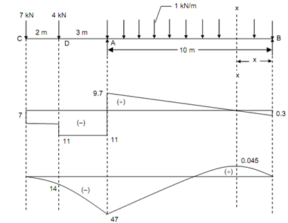
An overhanging beam of 15 m span is carrying a consistently distributed load of 1 kN/m over the length of 10 m at a distance 5 m from the left free end and point loads 7 kN and 4 kN, at free end and at a distance 2 m from the free end, respectively. Sketch the BMD and SFD for the beam. Situate the point of contraflexure.

Solution

Taking moments around B and equating to zero,

R A   × 10 - (7 × 15) - (4 × 13) - (1 × 10 × (10/2) ) = 0

RA = 20.7 kN

and      RB = 7 + 4 + (1 × 10) - 20.7 = 0.3 kN

Shear Force (beginning from the left end C)

SF just right of C, FC = - 7 kN

SF just left of D, FD = - 7 kN

SF just right of D, FD = - 7 - 4 = - 11 kN

SF just left of A, FA = - 11 kN

SF just right of A, FA = - 11 + 20.7 = 9.7 kN

SF just left of B, FB = + 9.7 - (1 ×10) = - 0.3 kN = Reaction at the support B.

Bending Moment      

BM at B, MB = 0

 BM at A, MA

= (0.3 × 10) - (1 × 10 × (10/2))  = - 47 kN m

BM at D, MD = - (7 × 2) = - 14 kN m

BM at C, MC  = 0

let a section XX at a distance x from the end B as illustrated in Figure.

Shear force at section XX,

Fx = - 0.3 + 1(x)

For maximum bending moment, shear force will be zero.

- 0.3 + x = 0

x = 0.3 m

We have,

Mx = + 0.3(x) - 1 × (x) ×(x/2) = 0.3x - x 2 /2

Mmax = 0.3 × (0.3) - ((0.3)2 /2) = + 0.045 kN m
1024_Evaluate the point of contraflexure.png

Figure

This is seen that the maximum negative bending moment take place at A and maximum positive bending moment take place at a distance 0.3 m from the right end B.

Mmax (positive) = + 0.045 kN m

Mmax (negative) = - 47 kN m

Point of Contraflexure

This is observed that the BM changes sign among A and B,

BM at any section XX,

Mx = 0.3 x - x 2 / 2

Equating this to zero,

0.3 x - x2/2      = 0

0.6 x - x2    = 0

∴          x = 0.6 m

Thus, the point of contraflexure is at a distance of 0.6 m from the right end B.


Related Discussions:- Evaluate the point of contraflexure

Calculate diameter of runner, A radically inward flow turbine working under...

A radically inward flow turbine working under a head of 10 m and running at 250 rpm develops 185 KW at the turbine shaft. At inlet tip of the runner vane, the peripheral velocity o

Maximum elastic torque - rectangular section, Maximum elastic torque: ...

Maximum elastic torque: A rectangular section torsion member had dimension of 100mm by 200 mm and is built of a steel for which the shear yield point is τ y = 100 MPa. Find o

Electromagnetic conversion device with example., Q.  In every electromagne...

Q.  In every electromagnetic conversion device, both generator and motor action take place simultaneously. Explain. The case the output is mechanical as in a motoring mode, th

Dynamics, a motorcycle is used to stunt show to go over a valley . if the i...

a motorcycle is used to stunt show to go over a valley . if the initial speed at A is u m/s, determine a. the minimum U so that the motorcycle reaches the bank at B. b. the veloc

Influence lines for the force, Solve the following two questions of the tru...

Solve the following two questions of the truss. Note that A and G are pin supports.  1)  Sketch the influence lines for the force in bar DG (the load is moving on the top chord

Home home, why 4R kinematic chain do not form different mechanisms?

why 4R kinematic chain do not form different mechanisms?

Structures of materials, what is the difference between atomic structure an...

what is the difference between atomic structure and crystal structure

Piping inspection and test plan, Q. Piping Inspection and Test Plan? Pi...

Q. Piping Inspection and Test Plan? Piping Inspection and Test Plan review and Piping Materials Test Results review shall be by the Piping Materials group, or by / with assista

What are the different theories of failure under static load, What are the ...

What are the different theories of failure under static load, explain briefly? The major theories of failure of a member subjected to bi-axial stress are as below: > Maximu

Equilibrium in concurrent force system - mechanics, Equilibrium in concurre...

Equilibrium in concurrent force system:   Sol.: The steps for solving problems of equilibrium in concurrent force system are as follows: 1.  First draw free body diagram

Write Your Message!

Captcha
Free Assignment Quote

Assured A++ Grade

Get guaranteed satisfaction & time on delivery in every assignment order you paid with us! We ensure premium quality solution document along with free turntin report!

All rights reserved! Copyrights ©2019-2020 ExpertsMind IT Educational Pvt Ltd