Evaluate the maximum bending stresses, Mechanical Engineering

Assignment Help:

Evaluate the maximum bending stresses:

A beam of I-section illustrated in Figure is simply supported over a span of 10 m. It carries an uniform load of 4 kN/m over the whole span. Evaluate the maximum bending stresses.

2444_Determine the maximum bending stresses1.png

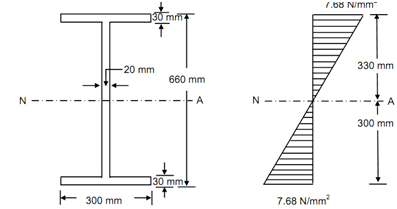
   Cross-section of Beam                 Bending Stress Distribution

Figure

Solution

Moment of inertia, I =1/12  (BD3 - bd3)

=          (1/12) (300 × 6603 - 280 × 6003)

= 21.474 × 108 mm4

Span of beam, l = 10 m

Uniformly distributed load, w = 4 kN/m

Maximum bending moment at the centre of beam, M = wl 2/ 8

Therefore,        M =4 × 10 2 / 8

= 50 kN m

= 5 × 10⁷ N mm

Neutral axis passes by the centroid of I-section.

 The distance of top and bottom layer from neutral axis, y = 330 mm


Thus, Bending stress, σ = (M / I )× y

= (5 × 10 7 / 21.474 × 10⁸ )× 330 = 7.68 N/mm2

So the bending stress at top and bottom layers = 7.68 N/mm2.


Related Discussions:- Evaluate the maximum bending stresses

Illustrate the importance of aesthetic consideration, You as design Enginee...

You as design Engineer, Describe how you would decide a suitable factor of safety for the design of a new mechanical elements. Illustrate the importance of aesthetic considerati

Example of reduce system to a single force and couple, Example of Reduce sy...

Example of Reduce system to a single force and couple: A system of parallel forces is acting on rigid bar as shown in the figure given below. Reduce this system to  a sing

Varignon, how should we consider positive or negative when summation of for...

how should we consider positive or negative when summation of forces

Describe classifications of instruments, Describe various classifications o...

Describe various classifications of instruments and differentiate between null type and deflection of instruments with suitable examples.

Milling, what is difference between slab milling and face milling ?

what is difference between slab milling and face milling ?

The leader command-autocad, The Leader Command The Leader command can b...

The Leader Command The Leader command can be used to annotate at any point on a drawing. The command sequence below was used to draw the leader shown in the Figure Below.

Find out the velocity of the bullet, Find out the velocity of the bullet: ...

Find out the velocity of the bullet: A bullet of weight W 1   = 5 N is fired into a body B 2 of weight W 2   = 45 N suspended by a string of length L = 1 metres. Because of i

Design the keys - shear keys, Design the keys - Shear Keys: A solid ci...

Design the keys - Shear Keys: A solid circular shaft is to transmit 200 kN at 200 rpm. If the maximum shear stress is not to exceed 80 n/mm 2 design the shaft. Design the key

Physics, show that the avogadro constant is the number of atoms in 0.072kg ...

show that the avogadro constant is the number of atoms in 0.072kg of carbon-12

Feathering system, what is feathering system in turbo prop type aircraft

what is feathering system in turbo prop type aircraft

Write Your Message!

Captcha
Free Assignment Quote

Assured A++ Grade

Get guaranteed satisfaction & time on delivery in every assignment order you paid with us! We ensure premium quality solution document along with free turntin report!

All rights reserved! Copyrights ©2019-2020 ExpertsMind IT Educational Pvt Ltd