Evaluate the deflection at the free end of the cantilever, Mechanical Engineering

Assignment Help:

Evaluate the deflection at the free end of the cantilever:

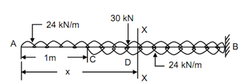
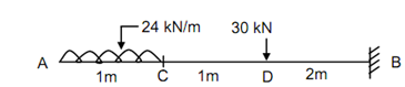
Discover the slope and deflection at the free end of the cantilever illustrated in Figure . Take EI = 200 × 106 N-m2.

Solution

Apply Udl in both the upward and downward directions in the portion CB.

1275_Evaluate the deflection at the free end of the cantilever.png

 Figure

477_Evaluate the deflection at the free end of the cantilever1.png

 Figure

M = - 24 x . (x/2) + 24 ( x - 1) (( x - 1)/2) - 30 [ x - 2]

= - 12 x2  + 12 [ x - 1]2  - 30 [ x - 2] --------- (1)

EI (d 2 y /dx2 )= M = - 12 x 2  + 12 [ x - 1]2 - 30 [ x - 2]        ----------- (2)

EI dy/ dx = - 4 x3 + 4 [ x - 1]3 - 15 [ x - 2] 2+ C1        --------- (3)

EIy =- x + [ x - 1] - 5 [ x - 2] + C1 x + C2            --------------- (4)

The boundary conditions are :

 At B, x = 4 m, dy/ dx  = 0         -------- (5)

At B, x = 4 m,  y = 0                       ----------- (6)

From Eqs. (3) and (5)

0 = - 4 × 4 3+ 4 (4 - 1) 3- 15 (4 - 2)3 + C1

∴          C1 = 208                   ----------- (7)

 From Eqs. (4), (6) and (7)

0 =- 4 4+ (4 - 1)4 - 5 (4 - 2) 3+ 208 × 4 + C2

∴          C2  = - 617                  --------- (8)

∴          EI (dy / dx )=- 4 x3  + 4 [ x - 1]3  - 15 [ x - 2]2  + 208         ---------- (9)

EIy =- x4  + [ x - 1]4  - 5 [ x - 2]3  + 208 x - 617-------- (10)

At free end A, x = 0, From Eq. (9)

 θ A = + 208 /EI = + 208 × 10/200 × 106 = + 1.04 × 10- 3  radians

From Eq. (10)

yA  =     617/EI = - 617 × 103 × 103 / 200 × 106 = - 3.085 mm ( ↓ )


Related Discussions:- Evaluate the deflection at the free end of the cantilever

Calculate the magnitude of forces, The greasted and least resultant of forc...

The greasted and least resultant of forces performing on a body are 35 KN and 5 KN respectively. Calculate the magnitude of forces. What could be the angle between these forces if

Gear box, how we can design a shaft for gear box

how we can design a shaft for gear box

Measurement of brake power by prony brake dynamiter, a) Illustrate with nea...

a) Illustrate with neat and clean diagram the measurement of brake power by prony brake Dynamiter OR Belt transmission type Dynamiter. b) A torsion dynamometer is fixed to a pro

Belt conveyors, Figure aside shows a belt conveyors which consists of...

Figure aside shows a belt conveyors which consists of endless belt. It has a power driven pulley at one end which moves the belt or downward flow of materials. General

Determine the speeds of gears, In a sun and planet type gear, the annular g...

In a sun and planet type gear, the annular gear (D) has 100 internal teeth, the sun gear (A) has 50 external teeth and a planet gear (B) has 25 external teeth. The gear (B) meshes

Illustrate about the term bearing capacity, Illustrate about the term beari...

Illustrate about the term bearing capacity? The bearing capacity of a soil mass frequently termed as the ability of the soil to carry the loads without any failure. The foun

Concept of centrifugal tension, Concept of centrifugal tension: Expl...

Concept of centrifugal tension: Explain concept of centrifugal tension in any belt drive. What is main consideration for taking maximum tension? Sol: T he belt continuo

Find the weight percent of austenite present in the steel, Find the weight ...

Find the weight percent of austenite present in the steel: A 0.4% C hypoeutectoid plain carbon steel is slowly cooled from 1540 o C to (i) slightly above 723 o C and (ii) s

Write Your Message!

Captcha
Free Assignment Quote

Assured A++ Grade

Get guaranteed satisfaction & time on delivery in every assignment order you paid with us! We ensure premium quality solution document along with free turntin report!

All rights reserved! Copyrights ©2019-2020 ExpertsMind IT Educational Pvt Ltd