Equipment parameter data, Electrical Engineering

Assignment Help:

Equipment parameter data:

The schematic diagrams for existing substations have to be prepared along with information of power transformer rating and numbers, impedance values, bus-bar scheme, isolators, circuit breakers type, for instance minimum oil/bulk oil/ SF6/Vaccum and kind of installation (indoor/outdoor), number of incoming and outgoing feeders, CTs and PTs, details of taps and normal tap position, spare bays, etc.

  • Load data covering the monthly, daily and yearly details of energy or peak power within the electrical system as well as the following information is needed:

1          Peak load on each transformer/feeder and corresponding actual voltage,

2          Diversity factor at several voltage levels,

3          Power factor at several voltage levels, and

4          Load factor and loss load factor at various voltage levels.

At last, the above points of entities are plotted on digitized maps. The network is modelled using a network mapping software and customized queries are built on the network database. Various layers of information such as the following are contained in these map representations.

  • The first layer corresponds to the land background containing roads, buildings, landmarks, rivers, railway crossings, etc.

1100_Equipment parameter data.png

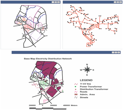
Figure: a) The Drawings of the Street Map of an Area; b) The Drawings of the Electricity Distribution Network; c) The Map of the Area overlaid with Electricity Distribution Network;


Related Discussions:- Equipment parameter data

Assembly language programming , Assembly Language Programming  In this...

Assembly Language Programming  In this   chapter  we will   discuss  programming  in assembly  language and  machine  language. The  difference  in machine  assembly  and high

Induction motor, A 100hp,460v,8pole,60hz,star connected 3phase IM runs at 8...

A 100hp,460v,8pole,60hz,star connected 3phase IM runs at 891rpm under full load what is the speed of the rotor field relative to i)rotor structure ii)stator rotating field

Compute the transfer function from the input, In this project we will consi...

In this project we will consider the control of a synchronous generator supplying electricity to the grid. We will focus on the problem of frequency stability. The frequency at whi

Time constant at decay of current, Time constant at decay of current In...

Time constant at decay of current In decay of current by an inductor, a method to find values of time constant similar as in rise of current through an inductor. The difference

Parallel operation of interconnected synchronous generators, Parallel Opera...

Parallel Operation of Interconnected Synchronous Generators In order to assure continuity of the power supplywithin prescribed limits of frequency and voltage at all the load p

Fet parameters, FET Parameters A basic, low-frequency hybrid-pi model ...

FET Parameters A basic, low-frequency hybrid-pi model for the MOSFET is displayed in figure. The several parameters are as follows. is the transconductance in siemens

Wye -delta conversion, how to write theory background on practical about t...

how to write theory background on practical about this topic.

Zener Diode, A Zener diode has the specifications VZ=6.8V and PDmax.=500mW....

A Zener diode has the specifications VZ=6.8V and PDmax.=500mW. Assume RZ=0. (a) Find the maximum allowable current iZ when the Zener diode is acting as a regulator. (b) If a sing

Use kcl and kvl to determine current, For the circuit shown in Figure, use ...

For the circuit shown in Figure, use KCL and KVL to determine i 1 , i 2 , v bd and v x . Also, find v eb .

Write Your Message!

Captcha
Free Assignment Quote

Assured A++ Grade

Get guaranteed satisfaction & time on delivery in every assignment order you paid with us! We ensure premium quality solution document along with free turntin report!

All rights reserved! Copyrights ©2019-2020 ExpertsMind IT Educational Pvt Ltd