Engine Vibration Indication
The engine vibration monitoring (EVM) system shows the out of balance force for the N1 and N2 shaft.
High engine vibration shows engine damage or other deviations in the engine. Vibration also reduces the comfort level in the aft passenger compartment.
Engine Vibration Monitoring System
The EVM system shows vibration in inches/second (IPS) An amber limit shows the maximum vibration level.
The EVM system has:
• a dual engine vibration transducer on each engine
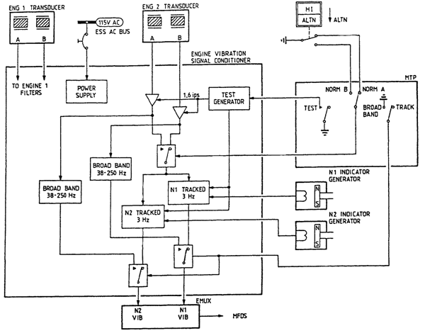
• an engine vibration signal conditioner
• a pushswitch on the overhead panel.
The vibration transducer has two internal vibration pick-ups, a pick-up A and B. each pick-up gives a voltage proportional to the acceleration or deceleration of the vibration.
The vibration transducer is on the IP compressor casing. This casing is the housing for bearings of the HP and LP shaft.
The engine vibration signal conditioner is a single unit for both engines. It processes the output of the engine vibration transducers for indication. The engine vibration signal conditioner gives two modes of vibration indication, tracked and broadband.
Tracked Indication
The tracked mode shows vibration of the N1 and N2 shaft. The engine vibration signal conditioner tunes two filters with an input of the N1 and N2 RPM indicator generators. Both filters connect to one pick-up of the vibration transducer, the other is standby. The VIB pushswitch on the ENGINE panel controls the active pick-up of the vibration transducer.
Broadband Indication
The broadband mode is an alternative mode. Vibration of the total power plant is shown. In this mode the output of both pick-ups in the vibration transducer goes through broadband filters. A semi-guarded switch selects the tracked or broadband mode.
Inte
