Engine speed indicators:
All engines have their rotational speed (R.P.M.) indicated. On a twin or triple-spool engine, the high pressure assembly speed is always indicated; in most instances, additional indicators show the speed of the low pressure and intermediate pressure assemblies. Where Engine Pressure Ratio (EPR) is not indicated then Low Pressure RPM is indicated as this can be corrected to give Thrust.
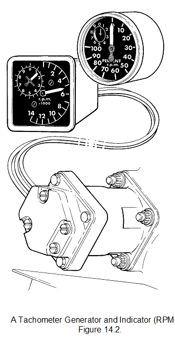
Engine speed indication can be electrically transmitted from a small tacho-generator, driven by the engine, to an indicator that shows the actual revolutions per minute (r.p.m.), or a percentage of the maximum engine speed. The engine speed is often used to assess engine thrust, but it does not give an absolute indication of the thrust being produced because inlet temperature and pressure conditions affect the thrust at a given engine speed.
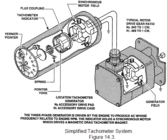
The tacho-generator supplies a three phase alternating current, the frequency of which is dependent upon engine speed. The generator output frequency controls the speed of a synchronous motor in the indicator, and rotation of a magnet assembly housed in a drum or drag cup induces movement of the drum and consequent movement of the indicator pointer.Tachometer generator systems have largely been replace by speed probes. A variable-reluctance speed probe, in conjunction with a phonic wheel, is used to induce an electric current that is amplified and then transmitted to an indicator (fig. 14.5.). This method can be used to provide an indication of r.p.m. without the need for a separately driven generator, with its associated drives, thus reducing the number of components and moving parts in the engine.
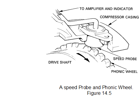
The speed probe can be positioned on the compressor casing in line with the phonic wheel, which can be a machined part of the compressor shaft. A gear wheel in an external gearbox can also be used. The teeth on the periphery of the wheel pass the probe once each revolution and induce an electric current by varying the magnetic flux across a coil in the probe. The magnitude of the current is governed by the rate of change of the magnetic flux and is thus directly related to engine speed.
On some engines one of the teeth is bigger than the others, and will give a bigger response. This can be used for Fan blade balancing or synchronising and/or synchrophasing.
In addition to providing an indication of rotor speed, the current induced at the speed probe can be used to illuminate a warning lamp on the instrument panel to indicate to the pilot that a rotor assembly is turning. This is particularly important at engine start, because it informs the pilot when to open the fuel cock to allow fuel to the engine. The lamp is connected into the starting circuit and is only illuminated during the starting cycle.
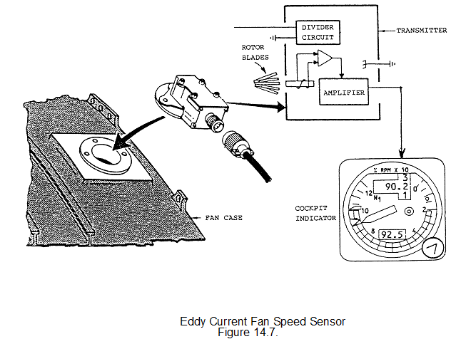
A variation of this system uses an eddy current sensor on the fan casing that senses the fan blades rotating. Sensors similar to these can be used for active tip clearance control, where it senses the gap between the casing and the blade.
Modern speed gauges usually have an analogue type display, i.e. a pointer, and also a digital readout below the pointer axis. A target speed indicator is usually fitted which on a clockwork gauge is a pointer outside the numbers, and on an electronic gauge as a coloured marker, this usually has a digital readout of its set position within the gauge normally above the pointer axis.