Engine protection devices - aircraft engine, Other Engineering

Assignment Help:

Engine protection devices :

Described below are typical protection devices that will override any excessive demands made on the engine by the pilot or by the control units.

TOP TEMPERATURE LIMITER.

Turbine gas temperature is measured by thermocouples in the jet pipe. When maximum temperature is reached, these pass a signal to an amplifier, which limits pump stroke by reducing pump servo pressure or moves the throttle valve in series with the pilot.
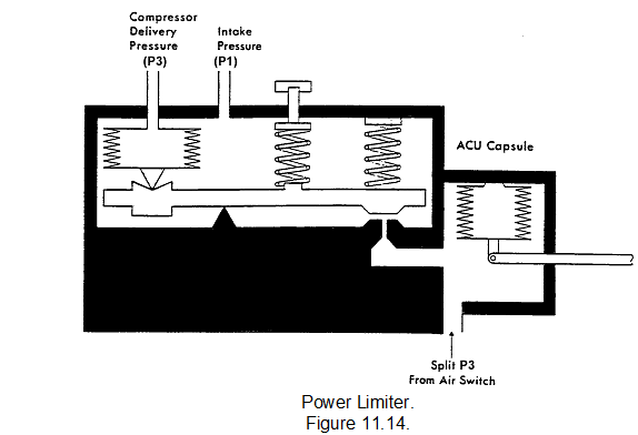
POWER LIMITER.

A power limiter is fitted to some engines to prevent over-stressing due to excessive compressor outlet pressure during high-speed, low altitude running. The limiter (see figure) takes the form of a half-ball valve which is opened against a spring force when compressor outlet press (P3) reaches its maximum value. The half-ball valve bleeds off air pressure to the ACU control capsule, thus causing the ACU to reduce pump stroke.

1399_engine protaction device.png

OVERSPEED GOVERNOR.

The engine is protected against over-speeding by a governor, which, in hydro-mechanical systems, is usually fitted on the fuel pump and acts by bleeding off pump servo fuel when the governed speed is reached. On two-spool engines, the pump is driven from the HP shaft and the LP shaft is protected by either a mechanical governor or an electro-mechanical device, again acting through the hydro-mechanical control system. There are two types of pump-driven governors:

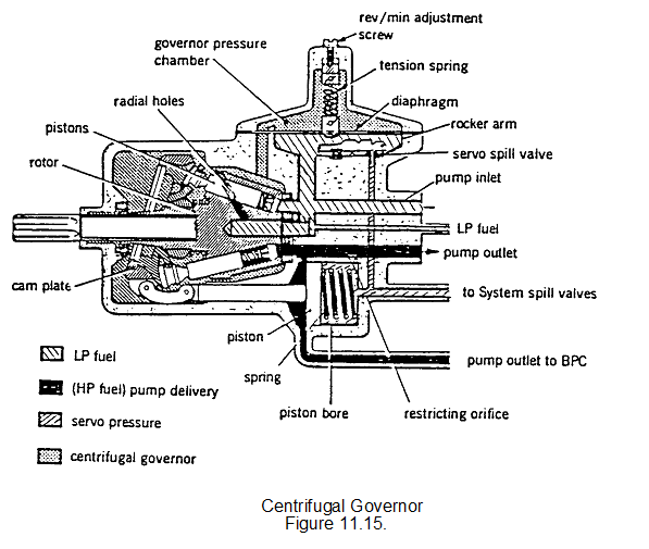
Centrifugal Governor.

The centrifugal type of governor uses the centrifugal pressure of fuel in radial drillings in the fuel pump rotor to deflect a diaphragm at maximum speed. The diaphragm operates on a half-ball valve to reduce pump servo pressure and thus pump stroke. The disadvantage of this type is that it needs to be reset if fuel specific gravity changes. It is seldom used on modern engines.
1115_engine protaction device1.png 
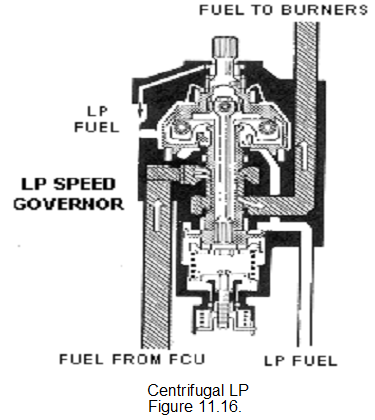
Centrifugal governors using bob weights are used as LP shaft governors on some engines. They will return fuel to low pressure when the LP shaft overspeeds see figure.

1934_engine protaction device2.png

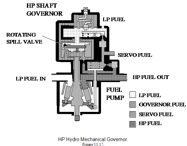
Hydro-mechanical Governor.

In the hydro-mechanical governor the pump drive shaft rotates a rotor containing a half-ball valve on a lever arm (shown in the figure). As engine speed increases, centrifugal force closes the valve, increasing the pressure of fuel in the governor housing (governor pressure) by restricting its flow to LP. When the maximum speed is reached, governor pressure is high enough to deflect a diaphragm, which opens the half-ball valve acting on pump servo. A hydro-mechanical governor does not require adjustment for changes in fuel specific gravity.

978_engine protaction device3.png


Related Discussions:- Engine protection devices - aircraft engine

The oil pressure indicator - aircraft engine, The oil pressure indicator : ...

The oil pressure indicator : The oil pressure indicator has a dial normally calibrated in pounds per square inch (psi). The indicator may have max. limit markers, but will alw

Meer, write drawback of linear array

write drawback of linear array

Aeroengines - fluent , Installing FLUENT on a MWS machine Fluent was origi...

Installing FLUENT on a MWS machine Fluent was originally developed on unix and graphical output was provided by calls to the X Windows graphics system For this reason provided by c

Installation of propeller, INSTALLATION OF PROPELLER The method of inst...

INSTALLATION OF PROPELLER The method of installation will depend on the type of propeller, and all instructions detailed in the appropriate AMM should be carefully followed; th

Capacitive transducers, Capacitive transducers Consider a capacitor con...

Capacitive transducers Consider a capacitor consisting of two parallel conducting plates with an insulator in between. Its capictance is C = ε 0 ε r  A/d where ε

Edc, Combination clipper

Combination clipper

Comparison of fp result with experiment, Comparison of FP result with exper...

Comparison of FP result with experiment At the lowest test lift coefficient the flow is just subcritical (in the sense that the Mach number of the flow component normal to the

Counter, Design a recycling MOD 19 up counter using JK FFs. In your design,...

Design a recycling MOD 19 up counter using JK FFs. In your design, include the logic circuit diagram and the timing diagram output that counts from 000002 = 010 to 100112 = 1910. C

#title., problem on dissociation constant

problem on dissociation constant

Adders and subtractors, Adders & Subtractors Adder and Subtractor circui...

Adders & Subtractors Adder and Subtractor circuits are used to perform basic calculations in computer systems. Adders, as their name suggests, add binary digits. Since binary

Write Your Message!

Captcha
Free Assignment Quote

Assured A++ Grade

Get guaranteed satisfaction & time on delivery in every assignment order you paid with us! We ensure premium quality solution document along with free turntin report!

All rights reserved! Copyrights ©2019-2020 ExpertsMind IT Educational Pvt Ltd