Engine indication systems in aircraft, Other Engineering

Assignment Help:

Engine indication systems in Aircraft:

Engine indications are very important to the crew of a powered aircraft, as they indicate one of the primary parameters needed for flight.

There are three types of indications:
1. Performance indications such as thrust (Engine Pressure Ratio EPR) and Revolutions Per Minute (RPM).
2. Operation indications such as Turbine Temperature indications, fuel flow, oil pressure and temperature.
3. Discrete indications which put ‘ON' a warning annunciator such as low oil pressure, fuel low pressure engine overspeed etc.

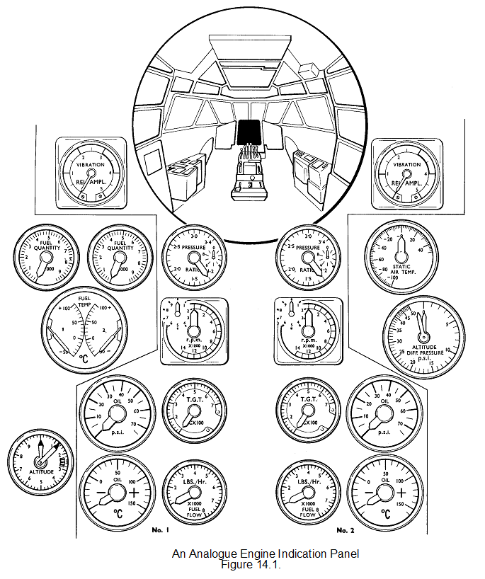
The engine instruments on most modern commercial aircraft will invariably be located on the main instrument panel in the centre, so that they are visible to both pilots. The instruments are laid out in a logical pattern so that the main thrust indicator is at or near the top of the indications. The indicators will be in vertical columns for each engine and like indicators in rows.

When a flight engineer is carried he will have a panel with some of the primary indications and all of the secondary and discrete indicators. He may also have a duplicate set of thrust levers so that he can trim engines when required.

Until fairly recently the majority of aircraft used analogue gauges (sometimes referred to as clockwork gauges) These had moving pointers or strips which indicated the parameter being monitored.

The modern trend is to replace the analogue instruments with electronic instruments that use LED, liquid crystal or cathode ray screens to display the engine parameters, often not displaying continuously all the information, but to highlight when a fault has occurred or when asked for by the crew. These types of instrument do not usually retain the last indication after an accident, however the electronic box powering them will inform the flight data recorder and/or retain the information in its own memory.

238_Engine indication systems in Aircraft.png


Related Discussions:- Engine indication systems in aircraft

#titleMetrics.., Suppose you are managing a software-development project fo...

Suppose you are managing a software-development project for which reliability is a major concern. A continual stream of anomalies is discovered in the software during the testing p

Electron gun, Electron gun: The electron gun consists of the following:...

Electron gun: The electron gun consists of the following: 1.  Cathode:  An indirectly heated cathode (negatively biased w.r.t. the screen). 2.  Grid:          A cylindric

Signal processing, why shift variant system causes artifacts

why shift variant system causes artifacts

Fibre optics communications, explain the fibre optic communication system w...

explain the fibre optic communication system with block diagram

PLC, True or False, In a PLC system, there is a physical connection between...

True or False, In a PLC system, there is a physical connection between field input devices and output devices.

Budget and determining, In Corporate finance, Experts engaged in this occup...

In Corporate finance, Experts engaged in this occupation have the liability to increase the organization's revenue, shareholder's money, investment spending budget and determining

Aerodynamics-flow model diagram , We will need to use several different flo...

We will need to use several different flow models as we go along. It is crucial to understand the simplifications used to obtain these models because these limit the validity of th

Imaging infrared seekers , Imaging Infrared Seekers  A more common appr...

Imaging Infrared Seekers  A more common approach is to use an infrared waveband where there is a large amount of ambient light from the thermal emission of the background. Th

Choked nozzle and thrust correction - turbojet, Choked Nozzle Consideri...

Choked Nozzle Considering the formula for thrust under "choked" nozzle conditions: Thrust =(P-P 0 )A + WV j /g     Where: P = Pressure P = Ambien

flow solver, Flow Solver The flow solver of FP utilises data produced ...

Flow Solver The flow solver of FP utilises data produced by the grid generator, together with data read from an input file named FLOW.DAT, and proceeds to calculate the solutio

Write Your Message!

Captcha
Free Assignment Quote

Assured A++ Grade

Get guaranteed satisfaction & time on delivery in every assignment order you paid with us! We ensure premium quality solution document along with free turntin report!

All rights reserved! Copyrights ©2019-2020 ExpertsMind IT Educational Pvt Ltd