Electronic engine control systems :
Advances in gas turbine technology have demanded more precise control of engine parameters than can be provided by hydromechanical fuel controls alone. These demands are met by electronic engine controls, or EEC, of which there are two types: supervisory and full-authority.
SUPERVISORY ELECTRONIC ENGINE CONTROL
The first type of EEC is a supervisory control that works with a proven hydromechanical fuel control.
The major components in the supervisory control system include the electronic control itself, the hydromechanical fuel control on the engine, and the bleed air and variable stator vane control. The hydromechanical element controls the basic operation of the engine including starting, acceleration, deceleration, and shutdown. High-pressure rotor speed (N2), compressor stator vane angles, and engine bleed system are also controlled hydromechanically. The EEC, acting in a supervisory capacity, modulates the engine fuel flow to maintain the designated thrust. The pilot simply moves the throttle lever to a desired thrust setting position such as full takeoff thrust, or maximum climb. The EEC adjusts the fuel flow as required to maintain the thrust compensating for changes in flight and environmental conditions. The EEC control also limits engine operating speed and temperature, ensuring safe operation throughout the flight envelope.
If a problem develops, control automatically reverts to the hydrome¬chanical system, with no discontinuity in thrust. A warning signal is displayed in the cockpit, but no immediate action is required by the pilot. The pilot can also revert to the hydromechanical control at any time.
Electronic Engine Control
A typical example of an EEC system is that used in many of the Pratt and Whitney 100 series engines currently in service. A brief explanation of how the system works, both in automatic and manual modes follows.
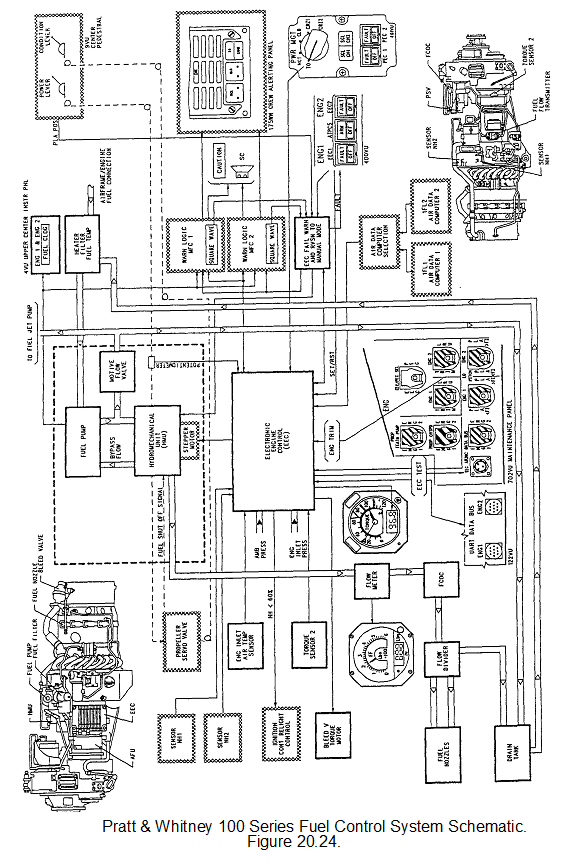
Automatic Operation (EEC mode)
The EEC receives signals from various sources:
a. Power Management Switch, enabling take off thrust, maximum continuous thrust, climb thrust or cruise thrust settings to be selected.
b. Engine inlet pressure and temperature.
c. Ambient pressure.
d. Air data computer inputs. (a computer that senses pitot pressure, static pressure and total air temperature)
e. Engine RPMs - N1 and N2.
f. Power lever position. (via a potentiometer)
g. Failure signals.
Based on these input signals the EEC will output command signals to adjust and control:
a. The Hydromechanical Fuel Control Unit via a stepper motor which adjusts the throttle metering valve.
b. Ignition circuits.
c. Bleed valves
d. Torque gauge