Electron gun:
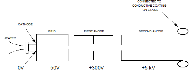
The electron gun consists of the following:
1. Cathode: An indirectly heated cathode (negatively biased w.r.t. the screen).
2. Grid: A cylindrical grid surrounding the cathode.
3. Anode: Two (sometimes three) anodes.
The cathode is a tube of metal closed at one end, with a coating of material that will emit electrons when heated, covering the closed end. To operate the cathode needs to be heated; this is achieved using a coil of insulated wire connected to the cathode.
Because the screen of the CRT contains conducting material at a high voltage (5 - 15kV), electrons will be attracted away from the cathode.
The free electrons have to pass through a pinhole in a metal plate (Control Grid). Altering the voltage of the grid can control the movement of the electrons through this hole. The voltage of the grid is always negative w.r.t. Cathode.
The free electrons are then formed into a beam by the action of the first anode. The anode is of a cylindrical shape and by adjusting the voltage on the anode, the beam can be made to come to a small point at the screen end of the CRT. The screen end of the CRT is coated with a material called a "Phosphor", which will glow when struck by electrons. The phosphor is usually coated with a thin film of aluminum so that it can be connected to the final accelerating (anode) voltage. The whole tube is formed as a vacuum.

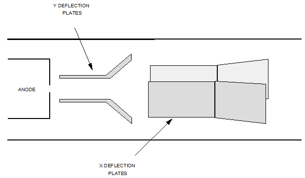
This arrangement will produce a point of light at the centre of the screen, but to make the CRT useful for displaying data, this beam of electrons must be able to be moved around the screen. For this, two sets of metal plates are used and if a voltage is passed through them, then the beam will deflect on the screen. These plates are called "Deflection Plates". These plates are arranged at right angles to each other. The beam can be deflected if a voltage is applied to these plates; this is called "Electrostatic" deflection. Movement of the beam left/right is controlled by the "X" Plates, with the "Y" Plates controlling movement up/down.

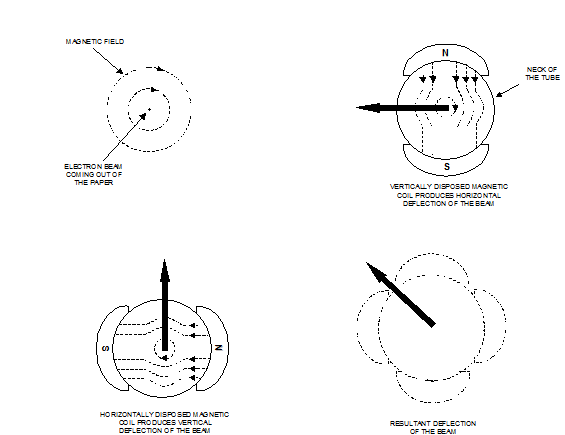
The other method used for deflection is Electromagnetic. This method is used for TV, computer monitors and most aircraft CRT displays. As an electron moves, it constitutes an electric current, and so a magnetic field will exist around it in the same way as a field around a current-carrying conductor.
In the same way that a conductor will experience a deflecting force when placed in a permanent magnetic field, so an electron beam can be forced to move when subjected to electromagnetic fields acting across the space within the tube. Coils are therefore provided around the neck of the tube, and are configured so that fields are produced horizontally (Y-axis field) and vertically (X-axis field). The coils are connected to the signal sources whose variables are to be displayed. The electron beam can be deflected to the left or right, up or down or along a resultant direction depending on the polarities produced by the coils, and on whether one alone is energised, or both are energised simultaneously.
