Effect of feedback on dynamic response and bandwidth, Electrical Engineering

Assignment Help:

Q. Effect of feedback on dynamic response and bandwidth?

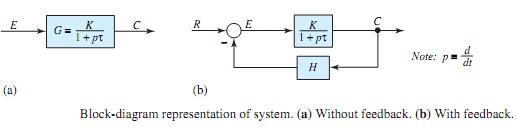
Let us consider the block-diagram representation of the open-loop system shown in Figure 16.2.5(a), whose direct transfer function is given by

1499_Effect of feedback on dynamic response and bandwidth.png

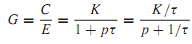
corresponding to which, the transient solution of the system is of the form given by

c(t) = Ae-t/τ

The transient in this system is seen to decay in accordance with a time constant of τ seconds. By placing a feedback path H around the direct transfer function, as shown in Figure (b), the closed-loop transfer function is then

2190_Effect of feedback on dynamic response and bandwidth1.jpg

2203_Effect of feedback on dynamic response and bandwidth2.png

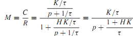
and the corresponding transient solution of the closed-loop system is of the form

cf (t) = Afe-[(1+HK)/τ ]t

where cf(t) represents the transient response of the output variable with feedback. Comparing Equations, it is clear that the time constant with feedback is smaller by the factor 1/(1 + HK), and hence the transient decays faster.

By treating the differential operator p as the sinusoidal frequency variable jω, i.e., p = jω = j(1/τ ), it follows from Equation that the bandwidth of the open-loop system spreads over a range fromzero to a frequency of 1/τ rad/s. On the other hand, for the system with feedback, Equation reveals that the bandwidth spreads from zero to (1 + HK)/τ rad/s, showing that the bandwidth has been augmented by increasing the upper frequency limit by 1 + KH.


Related Discussions:- Effect of feedback on dynamic response and bandwidth

Compute the attenuation, Q. A rectangular air-?lled RG-52/U is made of bras...

Q. A rectangular air-?lled RG-52/U is made of brass (ρ = 3.9 × 10⁻⁸ m) and has dimensions a = 22.86 mm and b = 10.16 mm. (a) Determine ¯ Z0(= R0) at the limits of the practica

Determine the peak magnetizing current, A forward converter has the followi...

A forward converter has the following parameters: input source voltage V s = 100 V, N 1 /N 2 = N 1 /N 3 = 1, magnetizing inductance L m = 5 mH, output inductor L o = 200 μH, C

Show the interconnections and appropriate polarity markings, Q. Two 1150:11...

Q. Two 1150:115-V transformers are to be inter connected for (a) 2300:230-V operation, and (b) 1150:230-V operation. Show the interconnections and appropriate polarity markings.

Compute the mutual inductance, Compute the mutual inductance: A long s...

Compute the mutual inductance: A long single layer solenoid has an effective diameter of 10 cm and it is wound with 1000 turns/m. There is a small concentrated coil with its p

RC coupled amplifier, what is the reason for reduction in low frequency and...

what is the reason for reduction in low frequency and high frequency regions in the frequency response of an Rc coupled amplifier?

Emitter bias, Emitter bias: Figure: Emitter bias While a ...

Emitter bias: Figure: Emitter bias While a split supply (dual power supply) is accessible, this biasing circuit is the very much effective, and gives zero bias vo

Evaluate reference voltage, Q. Consider the 4-bit R-2R ladder D/A converter...

Q. Consider the 4-bit R-2R ladder D/A converter with V ref =-10 V. Determine the analog output voltage when the binary input code is 1100. Also, find what reference voltage is to

Explain about subscriber loops signalling, Q. Explain about Subscriber loop...

Q. Explain about Subscriber loops signalling? In a telephone network, subscriber loop signal linger lies upon the kind of a telephone instrument used. The intra exchange signal

Write Your Message!

Captcha
Free Assignment Quote

Assured A++ Grade

Get guaranteed satisfaction & time on delivery in every assignment order you paid with us! We ensure premium quality solution document along with free turntin report!

All rights reserved! Copyrights ©2019-2020 ExpertsMind IT Educational Pvt Ltd