Dynamic movement in polar coordinates, Mechanical Engineering

Assignment Help:

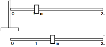
You are required to investigate the dynamic movement of a mass m sliding along a rod as shown in the diagram below. The rod is rotating at a constant angular velocity θ. The mass m is able to slide along the rod from position 1 (given by r = r1 to position 2 given by r = r2). At position 2 there is a stop as shown on the figure .Initially, at time t = 0, the mass m is tied by a string to the centre of rotation O which is then suddenly cut and frees the mass. At time t = 0, the angular position of the rod is θ = 0 rad. You are to neglect friction and the mass of the rod.

995_Dynamic Movement in Polar Coordinates.png

Notes:
Your own values of , r1, r2 and m are given in your Data Sheet

This investigation is to be carried out with your own specific data provided on a separate Data Sheet. No written material such as paragraphs or parts of text should be copied from any other source including your fellow students. All written text should be your own work.

Your tasks and corresponding marking scheme are as follows:

A. Draw the free body diagram of the forces on mass m at a position r between r1 and r2 and deduce the expressions for ar and aθ.

B. Determine the values of radial and tangential accelerations at position 1 just after cut-off of the string.

C. Determine the expressions for radial and tangential velocities for the mass m at any position r between r1 and r2.

D. Deduce the speed of the mass m when reaching position 2 and calculate the corresponding force involved when it stops at 2.

E. At t = 0.01 s, determine the angular and radial position of the mass as well as all the components of radial and tangential velocities and accelerations.

F. Explain why there is no such a thing as a centrifugal force.

G. If friction had been taken into account, what would be the relevant equations of motion. (do not solve them).

H. Report structure & presentation.


Related Discussions:- Dynamic movement in polar coordinates

What are the technical limitations of screw conveyer, What are the Technica...

What are the Technical Limitations of screw conveyer Technical Limitations: ? Turning limitation of this mechanism Actually the Maximum Turning of U-joint is 18° to 2

Withworth quick return mechanism, its definition, principle, explanation, a...

its definition, principle, explanation, application, and a diagram

Two wheeler, how to adjust the motorcycle clutch play

how to adjust the motorcycle clutch play

Mounting systems for the welding head-boom mounted type, Mounting Systems ...

Mounting Systems For The  Welding Head-Boom mounted type These are the most versatile type of welding systems. Normally the boom is supported by means of a column. The welding

Principle stresses, Determine the bending  (o-, ) and shear stress ( Tx), )...

Determine the bending  (o-, ) and shear stress ( Tx), ) at the surface element shown on the solid circular shaft below. Use Mohr's circle to determine the principle stresses, a l

Answer , define spring stiffness

define spring stiffness

Inventor claims in adiabatic system - mechanics, Inventor claims in adiabat...

Inventor claims in adiabatic system: On e inventor claims that 2 kg of air supplied to magic tube at 4 bar and 20°C and the two equal mass streams at 1 bar are produced, one

Opresion reserch, ppt of appling queuing model in railwy reservation

ppt of appling queuing model in railwy reservation

Synthesize a mechanism to prepare a function, Synthesize a mechanism to pre...

Synthesize a mechanism to prepare a function y = log x for 1≤ x ≤ 2 where three precision points are needed, for these precision points Calculate φ 2 , φ 3 and ψ 2 , ψ 3 ; if Δφ

Write Your Message!

Captcha
Free Assignment Quote

Assured A++ Grade

Get guaranteed satisfaction & time on delivery in every assignment order you paid with us! We ensure premium quality solution document along with free turntin report!

All rights reserved! Copyrights ©2019-2020 ExpertsMind IT Educational Pvt Ltd