Draw the circuit diagram of a Master-slave J-K flip-flop using NAND gates. What is race around condition? How is it eliminated in a Master-slave J-K flip-flop?
Ans.
Using NAND Gates logic Diagram of Master-Slave J-K Flip-Flop: Fig.(a) demonstrates the logic diagram of Master-Slave J-K Flip-Flop by using NAND gates.
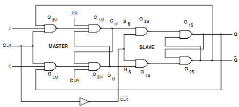
Fig.7(a) Logic Diagram of Master-Slave J-K FLIP-FLOP
The Race-around Condition: The difficulty of both inputs 1that means S = R = I being not permitted in an S-R Flip-Flop is removed in a J-K Flip-Flop through using the feedback connection from outputs to the inputs of the gates. There is into R-S Flip-Flop, the inputs do not change throughout the clock pulse (CK = 1), that is not true in J-K Flip-Flop due to the feedback connections. Notice that the inputs are J = K = 1 and Q = 0 and a pulse as demonstrated in Fig.(b) is applied to the clock input. After some time interval ?t equal to the propagation delay throughout two NAND gates in series, the output will be to Q = 1.
Now we contain J = K = 1 and Q = 1 and after other time interval of ?t the output will be back to Q = O. Therefore, for the duration tp of the clock pulse, the output will oscillate back and forth among 0 and 1. At the ending of the clock pulse, the value of Q is indefinite. This situation is termed to as the race-around conditions. So the race-around condition can be ignored if tp < ?t < T. Though, this may be not easy to satisfy this inequality due to very small propagation delays in ICs. A further practical method of overcoming such difficulty is the utilization of the master-slave (M-S) configuration.
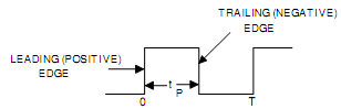
Fig. (b) a Clock Pulse
A master-slave J-K Flip-Flop is a cascade of two S-R Flip-Flops along with feedback from the outputs of the second to the inputs to the first as exemplified in Fig.(a). Positive (+ CLK) clock pulses are applied to the first Flip-Flop and the clock pulses are inverted before such are applied to the second Flip-Flop. While CK=1, the first Flip-Flop is enabled and the outputs QM and Q‾M act in response to inputs of theses i.e. J and K as per the Table. Now, the second Flip-Flop is inhibited since its clock is LOW ( = 0). While CK goes LOW (= 1), the first Flip-Flop is reserved and the second Flip-Flop is enabled, since now its clock is HIGH (= 1). Thus, the outputs Q and Q‾ follow the outputs QM and Q‾M respectively as in second and third rows of Table. Because the second Flip-Flop simply follows the first one, it is referred to as the Slave and the first one as the Master. Therefore, this configuration is termed to as Master-Slave Flip-Flop. In such circuit, the inputs to the gates G3M and G4M don't change throughout the clock pulse; therefore the Race-around condition does not be present. The state of the Master-Slave Flip-Flop changes on the negative transition (trailing ending).
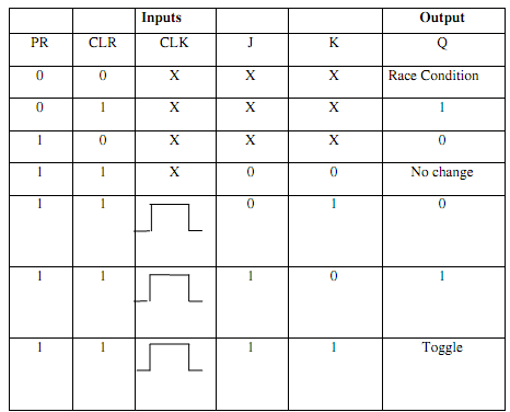
Table 7.1 Truth Table of JK Master-Slave Flip-Flop