Draw the bending moment diagram and shear force diagram, Mechanical Engineering

Assignment Help:

Draw the bending moment diagram and shear force diagram:

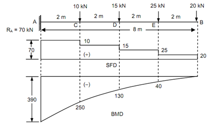
A cantilever beam of 8 m length is subjected to point loads of 15 kN, 10 kN, 25 kN and 20 kN at distances of 4 m, 2 m, 6 m and 8 m, respectively from the fixed end. Draw the bending moment diagram and shear force diagram.

Solution

Reaction at the support A = RA = 10 + 15 + 25 + 20 = + 70 kN.

Shear Force

SF at A = FA = + 70 kN

SF just left of C = + 70 kN

SF just right of C = + 70 - 10 = + 60 kN

SF just left of D = + 60 kN

SF just right of D = + 60 - 15 = + 45 kN

SF just left of E = + 45 kN

SF just right of E = + 45 - 25 = + 20 kN

SF just left of B = + 20 kN

SF just left of B = + 20 kN  (considering right side of the section)

2084_Draw the bending moment diagram and shear force diagram.png

Figure

 Bending Moment

BM at B, MB = 0         (since the moment at the free end is equal to zero)

BM at E, ME = - 20 × 2          (considering the right side)

                       = - 40 kN m

BM at D, MD = - (20 × 4) - (25 × 2)

                      = - 130 kN m

BM at C, MC  = - (20 × 6) - (25 × 4) - (15 × 2)       

                        = - 250 kN m

BM at A,   MA = - (20 × 8) - (25 × 6) - (15 × 4) - (10 × 2)

                             = - 390 kN m.


Related Discussions:- Draw the bending moment diagram and shear force diagram

Capacitor discharge welding, Capacitor Discharge Welding This is used ...

Capacitor Discharge Welding This is used for welding of studs, welding of thermocouples, etc. on the base metal. A low voltage, high amperage electrical discharge from a capac

Design for a water treatment plant, Design for a water treatment plant: ...

Design for a water treatment plant: Produce as individuals a single tab Excel spreadsheet which shows a rough initial design for a water treatment plant taking 15

Simulate the compression test, This assignment will simulate large deformat...

This assignment will simulate large deformations (nonlinear geometry) and occurrence of necking and buckling due to static tensile and compressive loading of a given elastic-plasti

Determine the loss-by-defect and loss-by-dispersion, Determine the loss-by-...

Determine the loss-by-defect and loss-by-dispersion Given, Annual production = 1,00,000 units Specification = 20 ± 4  i.e. m = 20, Δ = 4 Cost of repairing or resetting a

Inlet and exhaust valves-basic components of engine , Inlet and Exhaust Val...

Inlet and Exhaust Valves : Valves are commonly mushroom shaped poppet type. They are provided on the cylinder for regulation of the charge coming into the cylinder (inlet valve)

Hot service insluation thicknesses, Q. Hot Service Insluation Thicknesses? ...

Q. Hot Service Insluation Thicknesses? Hot Service Insluation Thicknesses are specified based on the following design criteria: • Average Annual Climatic Conditions:

Define the primitives of b-rep scheme, Primitives of b-rep Scheme The b...

Primitives of b-rep Scheme The building blocks for b-rep. models are : Vertex It is a unique point (an ordered triplet) in space. Edge An edge is a finite, non-

Show gasket compression, Q. Show Gasket Compression? Gasket compression...

Q. Show Gasket Compression? Gasket compression can also be used as a guide for limiting bolt torque. Spiral wound gaskets should be compressed to an average of 75% of origin

Supports for rigid bodies, Supports for Rigid Bodies: In this unit, yo...

Supports for Rigid Bodies: In this unit, you have learnt to classify various types of supports and constraints, rollers, rockers, ball and socket joints, cables, short links,

Write Your Message!

Captcha
Free Assignment Quote

Assured A++ Grade

Get guaranteed satisfaction & time on delivery in every assignment order you paid with us! We ensure premium quality solution document along with free turntin report!

All rights reserved! Copyrights ©2019-2020 ExpertsMind IT Educational Pvt Ltd