Draw shear force diagrams for the overhanging beam, Mechanical Engineering

Assignment Help:

Draw shear force diagrams for the overhanging beam:

Draw shear force & bending moment diagrams for the overhanging beam illustrated in Figure
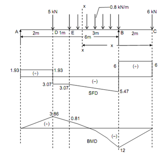
673_Draw shear force diagrams for the overhanging beam.png

Figure

 Solution

Taking moments around A & equating to zero,


RB   × 6 - (6 × 8) - 0.8 × 3 × ( 3 +(3/2))  - (5 × 2) = 0

RB = 11.47 kN and RA = 5 + (0.8 × 3) + 6 - 11.47 = 25 - 11.5 = 1.93 kN

Shear Force (beginning from the left end A)

SF at A, FA = + 1.93 kN

SF just left of D, FD = + 1.93 kN

SF just right of D, FD = + 1.93 - 5 = - 3.07 kN

SF at E, FE = - 3.07 kN

SF just left of B, FB = - 3.07 - (0.8 × 3) = - 5.47 kN

 SF just right of B, FB = - 5.47 + 11.47 = + 6 kN

SF just left of C, FC = + 6 kN = Load at E

Bending Moment

BM at C, MC  = 0

BM at B, MB = - 6 × 2 = - 12 kN m

 BM at E, M E =+ (11.46 × 3) - (6 × 5) -( 0.8 × 3 × (3/2) )=+ 0.81 kN m

BM at D, MD = + 1.93 × 2 = + 3.86 kN m

BM at A, MA = 0

Maximum Bending Moment

Maximum positive bending moment take place at D and maximum negative bending moment take place at B.

Mmax (positive) = + 3.86 kN m

Mmax (negative) = - 12 kN m

Point of Contraflexure

As the bending moment changes sign among E and B, let a section XX among E and B at a distance x from C.

BM at section XX,

Mx = - 6x + 11.47 (x - 2) - 0.8 (x - 2) ((x - 2)/2)

= - 6x + 11.47x - 22.94 - 0.4 (x - 2)2

= - 0.4x2 + 7.07x - 24.54

By equating this equation to zero, we achieved the point of contraflexure,

- 0.4x2 + 7.07x - 24.54 = 0

x2 - 17.67x + 61.35 = 0

Solving out by trial and error,

x = 4    Value of (x2 - 17.675x + 61.35) = 6.65

x = 4.9 Value of (x2 - 17.675x + 61.35) = - 1.2475

x = 4.8  Value of (x2 - 17.675x + 61.35) = - 0.45

x = 4.7 Value of (x2 - 17.675x + 61.35) = 0.3675

 x = 4.75 Value of (x2 - 17.675x + 61.35) = - 0.04375        

x = 4.745 Value of (x2 - 17.675x + 61.35) = - 0.00285

Point of contraflexure is at distance of 4.745 m from the end of C.


Related Discussions:- Draw shear force diagrams for the overhanging beam

Mechanical data for line designation tables, Line Designation Tables (LDT's...

Line Designation Tables (LDT's) (Appendix "D") are initially generated by the Piping designers. Design conditions are inputed by the Process discipline, and the Mechanical Engineer

Can you explain bentonite binders, Q. Can you explain Bentonite binders? ...

Q. Can you explain Bentonite binders? Its general composition is MgO.Al 2 O 3 .Sio 2 .H 2 O. it is formed by weathering of volcanic or igneous rocks. It is a creamy white powde

Create a suitable model with beam elements, The overall size of the crane m...

The overall size of the crane must not be changed. The height and reach of the loading point is to remain the same .  Original parts must remain and you are allowed additions such

Group technology, develop an appropriate group technology coding scheme for...

develop an appropriate group technology coding scheme for a line of machine screws using monocode. explain how the coding scheme works. Assume the product line has the following va

Manual metal arc-welding, Manual Metal Arc Welding Manual metal arc (MM...

Manual Metal Arc Welding Manual metal arc (MMA) welding, is a type of manual arc welding process that uses a consumable electrode coated with flux to lay the weld. An electric

Flight of the bumblebee, Flight of the Bumblebee Railroad train T a le...

Flight of the Bumblebee Railroad train T a leaves station A at a uniform speed of 30mph toward station B. Train Tb leaves station B at a uniform speed of 20mph toward station

Concept of torque speed variation in transmission system , Concept of Torqu...

Concept of Torque (Speed) Variation in Transmission System: When two different size gears are running at same speed, then the small gear makes more revolution than the big gear. T

Relations Among Load, 5. Calculate and draw the Shear force and Bending mom...

5. Calculate and draw the Shear force and Bending moment diagrams for the loaded beam and determine the maximum moment M and its location x from left end

Dynamic magnifier-forced vibration-synchronous whirl, Dynamic Magnifier: ...

Dynamic Magnifier: This is function of frequency ratio. Forced Vibration: While the system is continuously excited by an external force or internally produced force, the v

Write Your Message!

Captcha
Free Assignment Quote

Assured A++ Grade

Get guaranteed satisfaction & time on delivery in every assignment order you paid with us! We ensure premium quality solution document along with free turntin report!

All rights reserved! Copyrights ©2019-2020 ExpertsMind IT Educational Pvt Ltd