Draw bending moment diagram for the beam, Mechanical Engineering

Assignment Help:

Draw bending moment diagram for the beam:

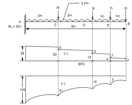
A cantilever beam carries a uniformly distributed load of 2 t/m over the total length of 6 m and point loads of 5 t, 3 t, 7 t & 2 t at a distance of 2 m, 4 m, 5 m, & 6 m, respectively from the fixed end. Draw BMD & SFD for the beam.

Solution

Reaction at the support A, RA = + 5 + 3 + 7 + 2 + (2 × 6) = 29 t

Shear Force : Starting from end A, SF at A, RA = 29 t

SF just left of C = + 29 - 2 × 2 = + 25 t

SF just right of C = + 25 - 5 = + 20 t

SF just left of D = + 20 - 2 × 2 = + 16 t

SF just right of D = + 16 - 3 = + 13 t

SF just left of E = + 13 - 2 × 1 = + 11 t

SF just right of E = + 11 - 7 = + 4 t

SF just left of B = + 4 - 2 × 1 = + 2 t

SF just right of B = + 2 t        (considering right side)

763_Draw bending moment diagram for the beam.png

Figure

Bending Moment : Starting from B,

 BM at B, MB = 0

BM at E, ME = - 2 × 1 - 2 × 1 × (½) = - 3 t m

BM at D, MD = - 2 × 2 - 7 × 1 - 2 × 2 ×(2/2) = - 15 t m

BM at C, MC  = - 2 × 4 - 7 × 3 - 3 × 2 - 2 × 4 ×(4/2) = - 51 t m

BM at A, MA = - 2 × 6 - 7 × 5 - 3 × 4 - 5 × 2 - 2 × 6 ×(6/2) = - 105 t m.


Related Discussions:- Draw bending moment diagram for the beam

Reinforced concrete design, You are tasked with the analysis and design of ...

You are tasked with the analysis and design of the gravity and wind framing system for a 6-story office building. A part plan of the building is attached.  The plan dimensions o

Explain about corrosion rates, Q. Explain about Corrosion Rates? Corros...

Q. Explain about Corrosion Rates? Corrosion rates of Corrosion data presented in these standards are in graphical form. The corrosion curves for the majority of the metals

Cooling period of furnace pipe, We shutdown our furnace and always encounte...

We shutdown our furnace and always encountered crack on our piping at the weld joints. I investigated that upon shutdown the furnace cracking, our maintenance immediately remove th

Estimate pump power and flow rate, In designing piping systems, it is somet...

In designing piping systems, it is sometimes desirable to estimate the appropriate pipe length for a given diameter, pump power and flow rate. In such cases, if minor pipe losses a

Evaluate the natural frequency, (a) Evaluate the natural frequency of syste...

(a) Evaluate the natural frequency of system shown in figure and show that it will be equal to (b) calculate equivalent stiffness of two springs connected in parallel.

Intrepretation of defects, INTREPRETATION OF DEFECTS Intrepretat...

INTREPRETATION OF DEFECTS Intrepretation is an important factor is controlling the quality of the product on economic levels. Sometimes for want of proper decision, proj

Multiple spot welding, Multiple Spot Welding This is a modification of sp...

Multiple Spot Welding This is a modification of spot welding, in which two or more than two welds can be obtained simultaneously from each transformer secondary. For specific pro

Prove the parallelogram law of forces - mechanics, Prove the parallelogram ...

Prove the parallelogram law of forces: Assume that the two forces P and Q act at a point ' O ' as shown in figure given below. The force P can be represented in magnitud

Write Your Message!

Captcha
Free Assignment Quote

Assured A++ Grade

Get guaranteed satisfaction & time on delivery in every assignment order you paid with us! We ensure premium quality solution document along with free turntin report!

All rights reserved! Copyrights ©2019-2020 ExpertsMind IT Educational Pvt Ltd