Draw bending moment diagram, Mechanical Engineering

Assignment Help:

Draw bending moment diagram:

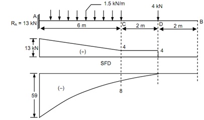
Draw the shear force diagram (SFD) & bending moment diagram (BMD) for the beam illustrated in Figure .

Solution

Reaction at the support A, RA = + 4 + (1.5 × 6) = + 13 kN.

Shear Force

SF at A, FA = + 13 kN (considering right side)

SF at C, FC = + 13 - 1.5 × 6

                      = + 4 kN

SF just left of D = + 13 - 1.5 × 6

                          = + 4 kN

SF just right of D = + 4 - 4 = 0
29_Draw bending moment diagram.png

Figure

Bending Moment

BM at B, MB = 0  (As, the moment at the free end is equal to zero)

BM at D, MD = 0 (letting right side of D, there is no loading on BD)

BM at C, MC = - 4 × 2 = - 8 kN m (- ve sign because of right anticlockwise)

BM at A, MA = - 4 × 8 - 1.5 × 6 ×(6/2) = - 59 kN m.


Related Discussions:- Draw bending moment diagram

Machine design, how an axial thrust is a generated in a helical gear

how an axial thrust is a generated in a helical gear

Determine the thermal efficiency, A combined cycle plant is designed to dev...

A combined cycle plant is designed to develop 200MW power. The air is obtained by the compressor at 300K and 1 bar pressure. The maximum temperature of the gas turbine cycle is lim

Thermodynamics, define the first and second law of thermodynamics.

define the first and second law of thermodynamics.

Composities, example with its properties

example with its properties

Describe the type of facing and backing sand, Q. Describe the type of Facin...

Q. Describe the type of Facing and Backing sand? Facing sand. This sand is used directly next to the surface of the pattern and comes into contact with the molten metal when th

Co2 gas supply-co2 welding, CO 2 Gas Supply The CO 2 shielding gas is...

CO 2 Gas Supply The CO 2 shielding gas is supplied cylinders at high pressure (140 kg / cm 2 ). Therefore pressure regulator and flow meter are connected to reduce the pressu

Calculate the shear flow in wall - flange areas, Calculate the shear flow i...

Calculate the shear flow in each wall of the fuselage section below. The flange areas are 1 sq in and the web thicknesses are 0.05 in. The material has modulus E = 10 mpsi and G =

Write Your Message!

Captcha
Free Assignment Quote

Assured A++ Grade

Get guaranteed satisfaction & time on delivery in every assignment order you paid with us! We ensure premium quality solution document along with free turntin report!

All rights reserved! Copyrights ©2019-2020 ExpertsMind IT Educational Pvt Ltd