Q. Draw and explain the circuit of Wein bridge oscillator. Obtain the expressions for the
(i) frequency of oscillation and (ii) condition for oscillation. Will oscillations take place if the bridge is balanced?
Wien bridge oscillator is one of the most popular type of oscillators used in audio and sub. audio frequency ranges (20 - 20 kHz). This type of oscillator is simple in design, compact in size, + Vcc and remarkably stable in its frequency output. Furthermore, its output is relatively free from distortion and its frequency OUTPUT can be varied easily. However, the maximum frequency output of a typical Wien bridge oscillator is only about 1 MHz. It employs two transistors, each producing a phase shift of 180, and thus producing a total phase-shift of 360 or 0degree.
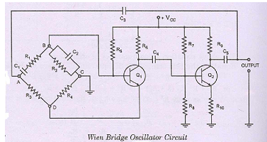
The circuit diagram of Wien bridge oscillator is shown in figure. It is essentially a two- stage amplifier with an R-C bridge circuit. R-C bridge circuit {Wien bridge) is a lead- lag network. The phase-shift across the network lags with increasing frequency and leads with decreasing frequency. By adding Wien-bridge feedback network, the oscillator becomes sensitive to a signal of only one particular frequency. This particular frequency is that at which Wien bridge is balanced and for which the phase shift is 0degree. If the Wien-bridge feedback network is not employed and output of transistor Q2 is fedback to transistor Ql for providing regeneration required for producing oscillations, the transistor Ql will amplify signals over a wide range of frequencies and thus direct coupling would result in poor frequency stability. Thus by employing Wien-bridge feedback network frequency stability is increased. In the bridge circuit Rl in series with Cl, R3' R4 and R2 in parallel with C2 form the four arms.
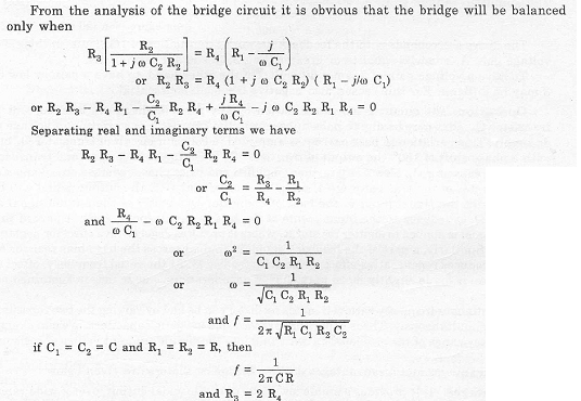
Thus we see that in a bridge circuit the output will be in phase with the input only when the bridge is balanced i.e., at resonant frequency given by expression (20.39). At all other frequencies the bridge is off-balance i.e. the voltage fedback and output voltage do not have the correct phase relationship for sustained oscillations.
So this bridge circuit can be used as feedback network for an oscillator, provided that the phase shift through the amplifier is zero. This requisite condition is achieved by using a two stage amplifier, as illustrated in fig. In this arrangement the output of the second stage is supplied back to the feedback network and the voltage across the parallel combination C2 R2 is fed to the input of the first stage. Transistor Ql serves as an oscillator and amplifier whereas the transistor Q2 as an inverter to cause a phase shift of 180°. The circuit uses positive and negative feedbacks. The positive feedback is through Rl' C1, R2' C2 to transistor Ql and negative feedback is through the voltage divider to the input of transistor Ql. Resistors Ra and R4 are used to stabilize the amplitude of the output.