Differential amplifier to eliminate the common-mode voltage, Electrical Engineering

Assignment Help:

Q. Differential amplifier to eliminate the common-mode voltage?

The transducer in some cases may have a local ground that cannot be disconnected. In such a case, a separate ground strap (braided-wire straps used because of their low inductance) is used to connect the local ground and the system ground point. The shield is also disconnected from the amplifier so as to prevent ground-loop current through the shield. Because the ground strap has nonzero resistance, any stray current through the strap will cause an interference voltage vcm known as common-mode voltage since it appears at both the transducer and the shield terminals.

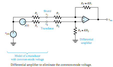
vcm is generally quite small; however, when the information-bearing signal voltage itself is rather small, the common-mode voltage may pose a problem, which can be eliminated by using the differential amplifier, as shown in Figure. The analysis with the virtual-short model of the op-amp reveals that

vout = K(v2 - v1)

amplifying the difference voltage v2 -v1.With reasonable assumptions that Rs << R1 and Rt << R2, we have v1 ≅ vcm and v2 ≅ x + vcm, so that

vout = K [(x + vcm) - vcm] = Kx

in which vcm has been eliminated as desired. Such an op-amp circuit is also known as an instrumentation or transducer amplifier.

Any interference at frequencies outside the signal band can be eliminated by appropriate filtering. However, in order to combat interference within the signal band (after proper shielding and grounding), a notch filter is sometimes used to avoid the bothersome interference at a single frequency f0. Figure illustrates the point: Part (a) shows the composite amplitude spectrum including the single-frequency interference; part (b) depicts the amplitude ratio of the notch filter.

The notch-filtering technique does, of course, introduce some inevitable signal distortion, and such filtering should precede amplification to prevent possible saturation of the amplifier due to the interference.

456_Differential amplifier to eliminate the common-mode voltage.png


Related Discussions:- Differential amplifier to eliminate the common-mode voltage

Write a report on various types of diodes, a. write a report (at least  2 p...

a. write a report (at least  2 pages ) on various types of diodes( Show and explain  the theory, symbol, circuit, characteristics, data sheets and applications circuits using the d

Calculate the resistance of the coil of a transistor, A 6 V / 2.5 mA relay ...

A 6 V / 2.5 mA relay is connected in the output stage of a transistor.  The coil is made of aluminium having α = 0.004. The resistance of the coil is 600 ? at 32 o C. Calculate th

Explain classification of amplifiers on biasing conditions, Q. Explain the ...

Q. Explain the classification of amplifiers on the biasing conditions? Based on the amount of transistor bias and amplitude of the input signal, amplifiers can be classified as

Find instantaneous electromagnetic torque, Consider an elementary two-pole ...

Consider an elementary two-pole rotating machine with a uniform (or smooth) air gap, as shown in Figure, inwhich the cylindrical rotor ismountedwithin the stator consisting of a ho

3-phase 120 degree mode vsi , 3-phase  120 0 Mode VSI In 1200 mode ...

3-phase  120 0 Mode VSI In 1200 mode VSI each thyristor  conducts for 1200. At a  time only  thyristor  one form  upper  group  and another  form group will conduct.  Only th

Electrical circuits and systems, Electrical circuits and systems : Elec...

Electrical circuits and systems : Electrical systems allow energy to be conveniently delivered from the point of supply to the point of application - e.g. electric railways, ca

Create a time diagram - conveyer, When the PLC is in the RUN mode it will s...

When the PLC is in the RUN mode it will switch ON the conveyer so it will run continuously. This project is divided into four outcomes: (a)    Detect block on entry, close

Draw the re-model for the circuit, Draw the re-model for the circuit given ...

Draw the re-model for the circuit given in figure and calculate: a). The input impedance (β=100), b). The output impedance (r0 = 50 kΩ) and c). The mid-band collector-base

Write Your Message!

Captcha
Free Assignment Quote

Assured A++ Grade

Get guaranteed satisfaction & time on delivery in every assignment order you paid with us! We ensure premium quality solution document along with free turntin report!

All rights reserved! Copyrights ©2019-2020 ExpertsMind IT Educational Pvt Ltd