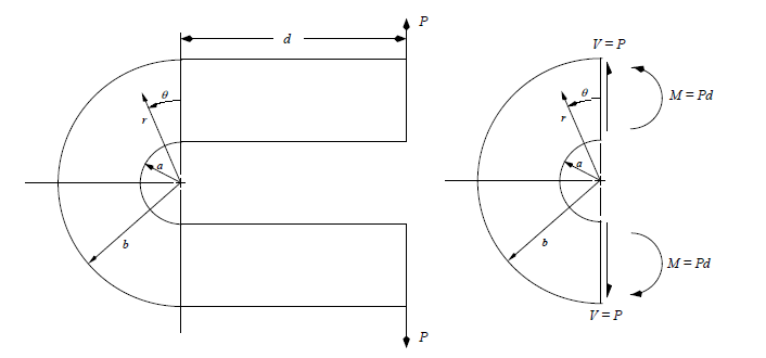
Consider the U-shaped curved beam shown below (with rectangular cross-section and thickness h), which is loaded by force P as indicated. A free-body diagram reveals that a moment M = Pd and shear force V = P are applied to the "curved section" of the beam, as shown.
Based on elasticity solutions for a curved beam (described on the following pages), develop a computer-based methodology* to generate plots of the following quantities along a cross-section located at an arbitrary angular position, Θ :
(a) The maximum principal stress, σ 1, vs radial position, r.
(b) The minimum principal stress, σ 2 , vs radial position, r.
(c) The angle between {the line of action of force P} and {the +1-axis}, vs radial position, r.
Use the following dimensions and load, and submit plots for the cross-section at Θ = 45° :
a = 1.0 in b = 3.0 in h = 0.125 in d = 7 in P = 240 lbf
