Determine the value of capacitance to give resonance, Electrical Engineering

Assignment Help:

Determine the value of capacitance to give resonance:

A circuit shown in Figure having a resistance of 5 Ω, an inductance of 0.4 H and a variable capacitance in series is connected across a 110 V, 50 Hz supply. Determine:

1.  The value of capacitance to give resonance

2.  Current

3.  Voltage across the inductance

4.  Voltage across the capacitance

5.  Q-factor of the circuit.

Solution

Applied Voltage, V = 110 V Resistance, 

R = 5 Ω Inductance, L = 0.4 Henry

Resonant frequency, f0 = 50 Hz

As Resonant frequency f0 = 1 /2π  √(LC)
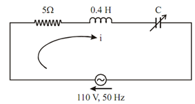
1708_Determine the value of capacitance to give resonance.png

Figure

 (a)       At resonant frequency capacitance

      C   = 1/4π (f0 )2 L = 1/ (4π  × (50)2 × 0.4)

       = 2.53303 × 10- 5

       = 25.3303 μF

 (b)       At resonant condition I = V/ R = 110/5.

                                                                       = 22 A

 (c)       Voltage across inductance = I XL = 22 × 2π × 50 × 0.4 = 2764.60 V.

 (d)       Voltage across capacitance = Voltage across inductance

                                                                  = 2764.60 V

 (e)       Q-factor = ω0 L/R = (2π f0 L )/ R         

= (2π × 50 × 0.4) /5

= 25.1327


Related Discussions:- Determine the value of capacitance to give resonance

What is the voltage gain, Q. What is the voltage gain? voltage gain is ...

Q. What is the voltage gain? voltage gain is the ratio of output voltage to input voltage. It is represented as Av,vo-voltage output,Vi-voltage input,Ic-collector current,Ie

Microprocessor, Memory map of tpa in a personal computer and explain such o...

Memory map of tpa in a personal computer and explain such of the areas in brief

Determine whether the systemnoise, The expression given in Problem for (S 0...

The expression given in Problem for (S 0 /N 0 )PCM is plotted for a sinusoidal message in Figure to show the performance curves for a PCM system using a polar waveform. (a) Comm

Give properties and uses of silicon and nickel iron alloys, Give the proper...

Give the properties and uses of silicon iron alloy and nickel iron alloy. Silicon Iron alloy: Pure iron has low resistivity that results in higher eddy current losses. These

Single sinusoid, Power up the "TIMS" unit by using the switch at the back. ...

Power up the "TIMS" unit by using the switch at the back. Connect the Pico Virtual Instrument (PicoScope) to the PC as per Appendix 1 On the "TIMS" unit, connect the 2 kHz (s

Find the sending end voltage and sending end current, A 3-phase transmissio...

A 3-phase transmission line is 200km long. The line has a per phase series impedance of 0.25+j0.45 Ω/km and shunt admittance of j7.2 μS/km. The line delivers 250MVA, at 0.6 lagging

Clampers, what would the change after adding a registor paralelly in clampe...

what would the change after adding a registor paralelly in clampers?

Transfer function of time multiplexer, How wood a transfer function of a ti...

How wood a transfer function of a time-multiplexer with switching in 10 kHz between 2 channels look like?

Obtain a thevenin equivalent circuit, Q. (a) Obtain a Thevenin equivalen...

Q. (a) Obtain a Thevenin equivalent circuit at terminals A-B in the circuit. (b) What impedance ¯ZL, when connected to A-B, produces maximum power in ¯ZL? (c) Find the val

Write Your Message!

Captcha
Free Assignment Quote

Assured A++ Grade

Get guaranteed satisfaction & time on delivery in every assignment order you paid with us! We ensure premium quality solution document along with free turntin report!

All rights reserved! Copyrights ©2019-2020 ExpertsMind IT Educational Pvt Ltd