Determine the normal stresses, Mechanical Engineering

Assignment Help:

Determine the normal stresses:

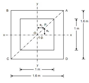
A short hollow pier 1.6 m × 1.6 m outsides as well as 1.0 m × 1.0 m intersides supports a vertical load of 2000 kN at a point located on a diagonal 0.5 m from the vertical axis of the pier. Determine the normal stresses at the 4 corners of the section of the pier, neglecting its self weight.
968_Determine the normal stresses.png

Figure

Solution

Figure illustrated the section of the pier. At point P, the load of 2000 kN is applied on the pier.

Area of cross-section A = 1.62 - 1.02 = 1.56 m2.

Section modulus, Z xx= Z yy 1.60 - 1.00 × (2/60) = 0.5875 m3

Eccentricity about XX-axis = Eccentricity around YY-axis

= 0.50 sin 45o = 0.353 m

Bending moment around XX-axis = Bending moment around YY-axis

= (2000 × 0.353)

= 706 kNm

Direct stress, f0  = P/ A =2000/1.56 = 1282.05 kN/m2  (compressive)

Bending stress around XX-axis = Bending stress around YY-axis

=± M/ Z =±     706 / 0.5785 = ± 1220.4 kN/m2

∴          Resultant stresses at corners,

f  = (P/ A) ± M xx/ Z xx ± M yy/ Z yy

Stress at corner A = 1282.05 + 1220.4 + 1220.4

                              = 3722.85 kN/m2 (compressive)

 Stress at corner B = 1282.05 - 1220.4 + 1220.4

                              = 1282.05 kN/m2 (compressive)

Stress at corner C = 1282.05 - 1220.4 - 1220.4

                           = - 1158.75 kN/m2 (tensile)

Stress at corner D = 1282.05 + 1220.4 - 1220.4

                              = 1282.05 kN/m2 (compressive)


Related Discussions:- Determine the normal stresses

Computer integrated manufacturing, the component of computer integrated man...

the component of computer integrated manufacturing with the diagram

Stearing system, advantanges of a fixedbeam over ackermann

advantanges of a fixedbeam over ackermann

Draw the bending moment diagram and shear force diagram, Draw the bending m...

Draw the bending moment diagram and shear force diagram: A cantilever beam of 8 m length is subjected to point loads of 15 kN, 10 kN, 25 kN and 20 kN at distances of 4 m, 2 m,

OPITZ alternative, I am looking for an alternative coding system to the OP...

I am looking for an alternative coding system to the OPITZ coding system for my essay thanks

Calculate the power angle, Question: A 3-phase, 15 kV, 4-pole, cylindri...

Question: A 3-phase, 15 kV, 4-pole, cylindrical rotor synchronous generator is connected to infinite bus running at 50 Hz. The synchronous reactance of the machine is X s = 0.

determine the minimum cross section area of graph, To design a cantilevere...

To design a cantilevered truss to support the loads shown in the figures, two layouts are proposed as shown in Figs. A and B. All truss members are steel with allowable stress of 2

Explain the tool signature, Explain the Tool Signature The tool angles ...

Explain the Tool Signature The tool angles have been standardized by the American standards association. The seven important elements comprise the signature of the cutting tool

MOS, limitations of euler''s theory

limitations of euler''s theory

Write Your Message!

Captcha
Free Assignment Quote

Assured A++ Grade

Get guaranteed satisfaction & time on delivery in every assignment order you paid with us! We ensure premium quality solution document along with free turntin report!

All rights reserved! Copyrights ©2019-2020 ExpertsMind IT Educational Pvt Ltd