Determine the maximum stress intensities, Mechanical Engineering

Assignment Help:

Determine the maximum stress intensities:

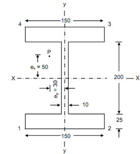
A rolled steel I-section, flanges 150 mm wide & 25 mm thick, web 200 mm long & 10 mm thick  is utilized to carry & axial load of 800 kN. The load line is eccentric, 50 mm above XX & 30 mm to the left of yy. Determine the maximum & minimum stress intensities in the section.

2349_Determine the maximum stress intensities.png

Figure


Solution

Area of the cross-section, A = 2 × (150 × 25) + (200 × 10) = 9500 mm2

Moment of inertia about XX-axis,

 I xx     = 150 × 250/12 - 140 (20)3/12

= 8565 × 104  mm4

Moment of inertia about YY-axis,

I yy =2 × (25 × 1503 )/ 12       -200 (10)3/12 = 1407 × 104  mm4

Eccentricity,

ex  = 50 mm

ey  =- 30 mm

Vertical load, W = 800 kN

Direct stress at any point, f0  = P/A    =800 × 103/9500

            = 84.2 N/mm2

Maximum bending compressive stress shall take place at edge 4 of the section in Figure

 = ( fb )4  = ((P × ex /Ixx) × y )+(( P × ey/ I yy )× x)

= (800 × 103 × 50/ 8565 × 104) × (- 125) +( 800 × 103 × (- 30) /1407 × 104) × 75

= 186.4 N/mm2

Maximum bending tensile stress shall take place at edge 2 at the section.

 ( f b )2  =( 800 × 10 3 × 50)/( 800 × 104 ))× (- 125)

                    +( 8565 × 103 (- 30)/ (1407 × 104 ))× 75

              = - 18.64 N/mm2

In the section Resultant stress would be as follows:

Maximum at corner 4 = 84.2 + 186.4 = 270.6 N/mm2

Minimum at corner 5 = 84.2 - 186.4 = - 102.2 N/mm2          (tensile)


Related Discussions:- Determine the maximum stress intensities

Spark plug -electrical system , Spark Plug: A spark jumps between the elec...

Spark Plug: A spark jumps between the electrodes of the spark plug when the voltage developed by the ignition system reaches the required value. This electrical spark occurs at a

Determine the concurrent forces, Determine the concurrent forces: Four...

Determine the concurrent forces: Four coplanar concurrent forces act at point and keep it at rest. These are mention in Figure. Determine the forces P and Q. Solution

Advantages of multiple vessels, Reduced costs result from failure Easier...

Reduced costs result from failure Easier fermenter planning (particularly in light of above) Easier downstream scheduling Off the shelf supplies e.g. motors Routine sup

Steady state conditions and the thermal equilibrium state, What is a differ...

What is a difference between the steady state conditions and the thermal equilibrium state? In steady state condition, temperatures are constant although heat transfer is taking

Find out dimension of the cross section of the beam, Q.  A wooden beam of t...

Q.  A wooden beam of the rectangular cross section is subjected to bending moment of 5KNm. If the depth of section is to be double the breadth and stress in wood is not to exceed 6

Find the diameter of drawn tubing , Find the diameter of drawn tubing ...

Find the diameter of drawn tubing (e = 0.0015 mm) to transport 0.002 m 3 /s of 20 o C water over 400 m length so that the head loss does not exceed 30m by using (

Draw the bending moment and shear force diagram, Draw the bending moment an...

Draw the bending moment and shear force diagram for the following cases : a) A cantilever beam of length (L) carrying a Point load (W)at its free end. b) A simply supported b

What is the net angle of twist at the free end, What is the net angle of tw...

What is the net angle of twist at the free end: The stepped steel shaft illustrated in Figure is subjected to a torque (T) at the free end and a torque (2T) in the opposite di

Chemistry, scale and sludge formation

scale and sludge formation

Write Your Message!

Captcha
Free Assignment Quote

Assured A++ Grade

Get guaranteed satisfaction & time on delivery in every assignment order you paid with us! We ensure premium quality solution document along with free turntin report!

All rights reserved! Copyrights ©2019-2020 ExpertsMind IT Educational Pvt Ltd