Determine the maximum stress developed in the beam, Mechanical Engineering

Assignment Help:

Determine the maximum stress developed in the beam:

An I section in Figure is utilized as a beam. The beam is subjected to a bending moment of 2.5 kN m at its neutral axis. Determine the maximum stress developed in the beam.

 1648_Determine the maximum stress developed in the beam.png

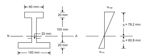
Beam Section                                 Bending Stress Distribution

Figure

Solution

 Assume 1713_Determine the maximum stress developed in the beam1.png be the distance of centroid from the bottom face.

Then, 1713_Determine the maximum stress developed in the beam1.png  =∑ ay / ∑ a

   1713_Determine the maximum stress developed in the beam1.png= ((100 × 20) ×10 + (20 ×100) × 70 + (60 × 20) ×130) /((100 × 20) + (20 ×100) + (60 × 20))

= 60.8 mm

 Moment of inertia of the section around the horizontal axis passing through the centriod,

I = [(1/12) ×100 × (20)3 + (100 × 20)(60.8 - 10)2 ]

+[ (1/12) × 20 (100)3 + (20 ×100)(70 - 60.8)2 ]

+ [(1/12) × 60 (20)3 + (60 × 20)(130 - 60.8)2 ]

= 1285.04 × 104 mm4

Topmost layer distance, yt = 140 - 60.8 = 79.2 mm

Bottommost layer distance, yb = 60.8 mm

∴          ymax = yt = 79.2 mm

 Through the relation,  M/ I = σ/ y

We obtain,       σmax = ( M/ I) × ymax

Bending moment,  M = 2.5 kN m

                                   = 2.5 × 106 mm

∴          σmax =  (2.5 × 10 6/1285.04 × 104)  × 79.2 = 15.41 N/mm

∴  The maximum bending stress in the beam = 15.41 N/mm2.


Related Discussions:- Determine the maximum stress developed in the beam

Mechanical design of the blowdown systems, Q. Mechanical design of the blow...

Q. Mechanical design of the blowdown systems? Mechanical design of the blowdown systems shall be sized for a continuous blowdown of a minimum of 1.0% of MCR. Fabricator may re

Explain parts of the machine of radial drilling, Major parts of the machine...

Major parts of the machine of Radial drilling machine Column The column is cylindrical in shape and built rugged and solid. The column supports the head and the sleeve or

Nature of bending stress, According to the explanation, why reverse will ha...

According to the explanation, why reverse will happen in the case of cantilevers? ( that is, tensile stresses will be induced in upper layers and compressive stresses will be induc

Mechanics, assumptions made in parallelogram law of forces

assumptions made in parallelogram law of forces

Mechanotechnics, list 5 important factors in the design of a workshops layo...

list 5 important factors in the design of a workshops layout

Supports for rigid bodies - space structures, Supports for Rigid Bodies (Sp...

Supports for Rigid Bodies (Space Structures): The primary step in solving equilibrium problems is to draw free-body diagram. Isolate the body through its surrounding. Replace

Relation between stress and strain, Relation between stress and strain: ...

Relation between stress and strain: The relation between stress and strain is generally shown by plotting a stress-strain (σ -e) diagram. Stress can be plotted on ordinate (ve

Mechanisms of machines, slidder crank chain / reciprocating engine mechanis...

slidder crank chain / reciprocating engine mechanism pics

Find out the moment of inertia of a triangular area, Find out the Moment of...

Find out the Moment of Inertia of a triangular area: Find out the Moment of Inertia of a triangular area ABC with base b and height d around its base BC. Therefore or otherwis

Write Your Message!

Captcha
Free Assignment Quote

Assured A++ Grade

Get guaranteed satisfaction & time on delivery in every assignment order you paid with us! We ensure premium quality solution document along with free turntin report!

All rights reserved! Copyrights ©2019-2020 ExpertsMind IT Educational Pvt Ltd