Determine the maximum bending moment, Mechanical Engineering

Assignment Help:

Determine the maximum bending moment:

A 12 m span simply supported beam is carrying a consistently distributed load of 2 kN/m over a length of 6 m from the left end and point loads 6 kN, 3 kN and 4 kN at distances of 7 m, 8 m and 9 m, respectively. Draw BM diagram and SF diagram for the beam and determine the maximum bending moment.
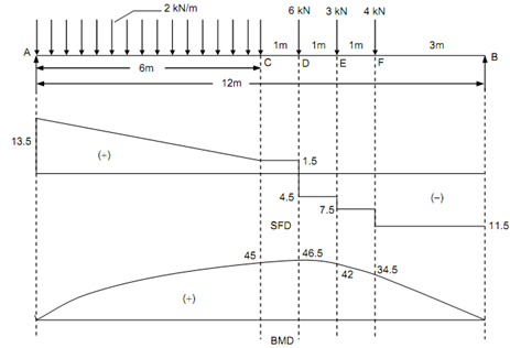
2454_Determine the maximum bending moment.png

Figure

Solution

Taking moments around A, and equating to zero.

RB × 12 - (4 × 9) - (3 × 8) - (6 × 7) - 2 × 6 ×(6/2)   = 0

Therefore,        RB = 11.5 kN, and

RA = (2 × 6) + 6 + 3 + 4 - RB = 25 - 11.5 = 13.5 kN

Shear Force (beginning from the left end)

 SF at A, FA = + 13.5 kN

SF at C, FC = + 13.5 - 2 × 6 = + 1.5 kN

SF just left of   D = + 1.5 kN

 SF just right of D = + 1.5 - 6 = - 4.5 kN

SF just left of  E = - 4.5 kN

SF just right of E = - 4.5 - 3 = - 7.5 kN

 SF just left of   F = - 7.5 kN

SF just right of F = - 7.5 - 4 = - 11.5 kN

SF just left of   B = - 11.5 kN = Reaction at B.

Bending Moment

BM at A, MA = 0

BM at C, M  = (13.5 × 6) - 2 × (6 ×(6/2))   = 45 kNm (considering left side)

BM at D, MD = (11.5× 5) - (4 × 2) - (3 × 1) = 46.5 kN m (considering right side)

BM at E,

ME = (11.5 × 4) - (4 × 1) = 42 kN m

BM at F,

MF = (11.5 × 3) = 34.5 kN m

The maximum bending moment take place at D where the shear force changes sign.

                       Mmax = 46.5 kN m.


Related Discussions:- Determine the maximum bending moment

Plate clutch pressure-clutch slipping, Plate clutch pressure:  Check plate...

Plate clutch pressure:  Check plate clutch pressure for any step using a straight edge.

Subcontractor submittals, The Supplier/Subcontractor shall submit, for acce...

The Supplier/Subcontractor shall submit, for acceptance, their Material Traceability and PMI program and procedures, which shall comply with this specification, prior to the sourci

Initial tension in the belt, Initia l Tension in The Belt: Let T o =...

Initia l Tension in The Belt: Let T o = initial tension in belt T 1  = Tension in tight side T 2  = Tension in slack side T C  = Centrifugal Tension in belt T

Illustrate thermal and hydrodynamic boundary layer, Define different regime...

Define different regimes of boiling and depict their ranges on a excess temperature curve us heat flux. Also distinguish between laminar film condensation and dropwise condensation

Arc welding power sources-arc characteristics, ARC CHARACTERISTICS In ...

ARC CHARACTERISTICS In order to understand the different output characteristics that are required by the welding power source it is necessary to understand the load which is f

Centre of gravity and moment of inertia, Centre of Gravity and Moment of In...

Centre of Gravity and Moment of Inertia: -  For a uniform plate of mass M, the overall mass may be divided into individual masses M i for which centre of gravity is known as

What is the procedure of carburettor cleaning?, (a) What may happen if carb...

(a) What may happen if carburettor is not serviced at a regular interval? (b) What is the procedure of carburettor cleaning?

Foil butt seam welding, Foil Butt Seam Welding This is a modification o...

Foil Butt Seam Welding This is a modification of seam welding, in which thin narrow strips of metal arc introduced between one or both of the circular electrodes and the work p

Rigid bodies, A sign of uniform density weighs 270 lb and is supported by a...

A sign of uniform density weighs 270 lb and is supported by a ball-andsocket joint at A and by two cables. Determine the tension in each cable and the reaction at A.

Write Your Message!

Captcha
Free Assignment Quote

Assured A++ Grade

Get guaranteed satisfaction & time on delivery in every assignment order you paid with us! We ensure premium quality solution document along with free turntin report!

All rights reserved! Copyrights ©2019-2020 ExpertsMind IT Educational Pvt Ltd