Determine the loading on the beam, Mechanical Engineering

Assignment Help:

Determine the loading on the beam:

Shear force diagram for a loaded beam is illustrated in Figure. Determine the loading on the beam & therefore, draw the bending moment diagram. Situate the point of contraflexure, if any.

Solution

Let us analyse the shear force diagram specified in given Figure .

At A

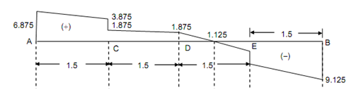
The shear force diagram enhance suddenly from 0 to 6.875 kN in upward direction, at A. This denote that there is support at A, along magnitude of reaction 6.875 kN.

Between A and C

The SF diagram is an inclined straight line among A and C. It denotes that there is a uniformly distributed load among A and C. The load enhance from 6.875 kN to 3.875 kN (6.875 kN - 3.875 kN = 3 kN). Therefore, the beam carries a uniformly distributed load of   3/1.5= 2 kN/m among A and C.

At C

The shear force diagram suddenly reduces from 3.875 kN to 1.875 kN. It denote that there is a point load of 2 kN (3.875 kN - 1.875 kN) working in downward direction at C.

1987_Determine the loading on the beam.png

Figure

Between C and D

As the shear force diagram is horizontal among C and D, there is no load among C and D.

Between D and E

The SF diagram is an inclined straight line among D and E. It denotes that there is a uniformly distributed load. Load reduction from + 1.875 kN to - 1.125 kN. Thus, the beam carries a uniformly distributed load of (+1.875 + 1.125 = 3 kN) ⇒ 3/1.5= 2 kN/m between D and E.

At E

 The shear force diagram has sudden reduce from - 1.125 kN to - 6.125 kN. It denotes that there is a point load of 5 kN (↓) at E.

Between E and B

The SFD reduce from - 6.125 kN to - 9.125 kN by an inclined straight line, that shows that the beam carries a u.d.l. of   3 /1.5 = 2 kN/m among E and B.

At B

As there is a sudden enhance from - 9.125 kN to 0 at B, there is a support at B of reaction 9.125 kN.

Bending Moment

BM at A,         MA = 0

BM at C,           M C    = (6.875 × 1.5) - (2 × 1.5 × (1.5/2) )  = 8.06 kN-m

BM at D ,  M D  = (6.875 × 3) - 2 × 1.5 × 2.25 = (- 2 × 1.5) = 10.875 kN-m

BM at E,  M = (9.125 × 1.5) - ( 2 × 1.5 × (1.5/2)   = 11.44 kN-m

Maximum Bending Moment

Let a section XX among D and E at a distance x from the end B. SF at section XX,

Fx  =- 9.125 + 5 + 2 x - 4.125 + 2 x = 0

∴ x = 2.0625 m  (for maximum BM)

∴ M max            = (9.125 × 2.0625) - 5 × (2.0625 - 1.5) - ( 2 × 2.0625 × (2.0625/2) )

= 11.75 kN-m


Related Discussions:- Determine the loading on the beam

Rotary converters, ROTARY CONVERTERS Historically, these type of power so...

ROTARY CONVERTERS Historically, these type of power sources were developed first for arc welding applications and even now these types are popular. These rotary converters are of

Angle of twist is zero on the shaft, Angle of twist is zero on the shaft: ...

Angle of twist is zero on the shaft: A shaft 10 m long and 100 mm diameter during its length is fixed at the ends and is subjected to two opposite torques of 8 kN-m and 10 kN-

Painting of structural components of skid, Q. Painting of structural compon...

Q. Painting of structural components of skid? Sandblasting and priming shall be carried out prior to assembly, and shall include all bolt holes, flange faces, etc. Flange gaske

Determine moment of the force about the origin, (a) What do you understand ...

(a) What do you understand by couple moment. Is it a free vector ? (b) A force F = 10i + 6j - 6k N performs at a position (10, 3, 4) m relative to a coordinates system. Determin

Find the stresses by finite method, The stepped bar in Fig Q6 is stretched ...

The stepped bar in Fig Q6 is stretched along the vertical axis and the maximum upward displacement is found to be 0.008 m. The bar has cross-sectional areas of A 1 and A 2 ov

Drag link mechanism, why there is a different angular velocity in the two c...

why there is a different angular velocity in the two cranks of a drag link mechanism?

Scope of pipeline systems, Q. Scope of pipeline systems? This specifica...

Q. Scope of pipeline systems? This specification covers the specific materials, surface preparation, method of application, quality assurance, and repair necessary for the appl

Plate clutch for warpage-clutch jerking, Plate clutch for warpage : Place ...

Plate clutch for warpage : Place plate clutch on surface plate and check for warpage. Ensure that 0.20 mm feeler gauge does not slide freely.

Define principal process for electron beam machining, Define Principal Proc...

Define Principal Process for Electron Beam Machining A beam of electrons is emitted from the electron gun which is basically following three points. 1. A cathode whic

Write Your Message!

Captcha
Free Assignment Quote

Assured A++ Grade

Get guaranteed satisfaction & time on delivery in every assignment order you paid with us! We ensure premium quality solution document along with free turntin report!

All rights reserved! Copyrights ©2019-2020 ExpertsMind IT Educational Pvt Ltd