Determine the deflection under the loads, Mechanical Engineering

Assignment Help:

Determine the deflection under the loads:

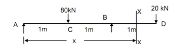
Determine the deflection under the loads as shown in Figure

1650_Determine the deflection under the loads.png

Solution

∑ Fy  = 0, so that RA + RB  = 80 + 20 = 100 kN          -------- (1)

Σ M about A = 0.

80 × 1 + 20 × 3 = RA × 2  ∴ RB  = 70 kN (↑)

From Eqs. (1) and (2),

RA = 30 kN ( ↑ )              ------------ . (2)

M = 30 x - 80 ( x - 1) + 70 ( x - 2) -------- (3)

EI (d 2 y /dx2) = M = 30 x - 80 [ x - 1] + 70 [ x - 2]         ------------- (4)

EI dy/ dx = 15 x - 40 [ x - 1]2 + 35 [ x - 2]2 + C1                   --------- (5)

 EIy = 5 x3  - 40 [ x - 1]3  + 35 [ x - 2]3  + C x + C      --------- (6)

The boundary conditions are :

 At A, x = 0,     y = 0                               -------- (7)

At B, x = 2 m,    y = 0                    -------- (8)

From Eq. (6) and (7), C2 = 0

From Eqs. (6) and (8)

0 = 5 × 23  - 40 [2 - 1]3  + C1  × 2

C1  =- 40 /3

∴          EIy = 5 x3 - (40/3) [ x - 1]3  + (35/3) [ x - 2]3  - (40/3) x        . . . (7)

Deflection at C,

x = 1 m

EIyC      = 5 × 13  - (40/3) × 1 = - 25/3

∴          yC = - 25 /3 EI                    --------------- (8)

Deflection at D,

x = 3 m

EIy D     = 5 × 33  - (40 /3)(3 - 1)3  + 35 (3 - 2)3  - (40 /3)× 3 = 0

YD= 0


Related Discussions:- Determine the deflection under the loads

Tool geometry, why single point cutting tool used in lathe

why single point cutting tool used in lathe

What are the conditions where combined footings used, What are the conditio...

What are the conditions where combined footings used? Two conditions in which it is used are as: a. When an exterior column is immediately adjacent to a property or mechanic

Explain the side relief angle, Explain the Side Relief Angle It is angl...

Explain the Side Relief Angle It is angle made by flank of a tool and plane perpendicular to base just under the side cutting edge. if the side relief angle is very large the c

Disc type brake, Disc Type Brake:  As shown in Figure the disc brake ...

Disc Type Brake:  As shown in Figure the disc brake consists of a pearlitic grey cast iron disc bolted to the wheel hub and a stationary housing called caliper. Casting in tw

Pre heat interpass temp. requirements for filler metals, PRE HEAT INTERPASS...

PRE HEAT INTERPASS TEMP. REQUIREMENTS FOR FILLER METALS The preheat and inter pass temperature must be sufficient to prevent the  cracking.Previous  Experience has shown that t

Counterclockwise direction, Figure presents a gearbox that you are going to...

Figure presents a gearbox that you are going to design. The input shaft rotates at n1= 1500 rpm in a counterclockwise direction. The gearbox is needed to be designed sothat the out

Flux shielded arc welding, FLUX SHIELDED ARC WELDING This process is p...

FLUX SHIELDED ARC WELDING This process is popularly known as Submerged Arc Welding (SAW).This is a fully mechanised welding process. The electrode is a continuous metallic sol

Means of starting -kick starting -self-starting , Means of Starting ...

Means of Starting Kick Starting A kick lever is used to crank the engine. When we crank the engine, the air-fuel mixer is sucked into the engine and pressure builds in

Beam, calculate the vertical reaction at A in Newtons

calculate the vertical reaction at A in Newtons

Bevel gear and shaft analysis, I have a bevel gear and shaft and I want to ...

I have a bevel gear and shaft and I want to know the maximum load that can be applied on it. also I have no information about it, what kind of information is needed for this calcul

Write Your Message!

Captcha
Free Assignment Quote

Assured A++ Grade

Get guaranteed satisfaction & time on delivery in every assignment order you paid with us! We ensure premium quality solution document along with free turntin report!

All rights reserved! Copyrights ©2019-2020 ExpertsMind IT Educational Pvt Ltd