Determine flux in the central limb, Electrical Engineering

Assignment Help:

Determine flux in the central limb:

For the magnetic circuit shown in Figure the value of flux in the right limb is 0.48 m Wb and the number of turns wound on the central limb is 1000. Determine (a) flux in the central limb, and (b) the current needed.

The magnetiSation curve for the core is specified as below:
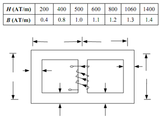
1526_Parallel Magnetic Circuit1.png

Figure

Solution

Area of cross-section in side limbs = 4 × 3 =12 cm2

Area of cross-section in core = 4 × 3 = 12 cm2

Flux in side limbs = 0.48 m Wb

Flux density in side limbs = (0.48 × 10)/ (12 × 10- 4)

                                               = 0.4 Wb/m2

For the flux density of 0.4 Wb/m2, H = 200 AT/m

Since the coil is wound on the central limb and the magnetic circuit is symmetrical, flux in the central limb = 2 × 0.48 = 0.96 m Wb.

Flux density in the central limb = 0.96 × 10/12 × 10- 4 = 0.8 Wb/m2

For the flux density of 0.8 Wb/m2, H = 400 AT/m

Side limb contain a path of length 50 cm. Central limb contain a path of length 20 cm.

Total m.m.f required = H× length = 200 × 50 × 10- 2 + 400 × 20 × 10- 2 = 180 AT

Current required =180/1000 = 0.18 Amp .


Related Discussions:- Determine flux in the central limb

Give a few applications of superconductors, Give a few applications of supe...

Give a few applications of superconductors. Also give three applications of superconductors. Application of superconductors in Electrical and Electronic Engineering (i) The

Semiconductors, Why do potential barriers breaks when a breakdown voltage i...

Why do potential barriers breaks when a breakdown voltage is application to semiconductor

Induction motor, A very widely used alternative form of synchronous motor i...

A very widely used alternative form of synchronous motor is the  ' indu c tion motor'. This has the advantage that it does not require an auxiliary motor to run the rotor up t

Circuit board packaging, Topics for the projects 1. Power supply design:...

Topics for the projects 1. Power supply design: One source, multiple source. Project process: 1.  Design(circuit analysis, diagram, list of components). 2.   Hardware e

Define the time constant of the circuit, A coil of inductance 0.04 H and re...

A coil of inductance 0.04 H and resistance 10? is connected to a 120 V, d.c. supply. Verify (a)  The final value of current     (b)  The time constant of the circuit (c)

History - field-effect transistor, History - Field-Effect Transistor: ...

History - Field-Effect Transistor: The principle of field-effect transistors was very first patented by Julius Edgar Lilienfeld in the year 1925 and by Oskar Heil in the year

Describe what you understand by offset voltage, a. Describe what you unders...

a. Describe what you understand by 'offset voltage' and 'offset current' of op-amp.  Discuss with a neat circuit diagram the method used for minimizing offset voltage and offset cu

Digital electronics, A universal shift register can shift in both the left-...

A universal shift register can shift in both the left-to-right and right-to-left directions, and it has parallel-load capability. Draw a circuit for such a shift register.

Modern physics, jsidjsiod dkndkdisd dknssbs bsjbabd asj u dhihf ujojdsajfs...

jsidjsiod dkndkdisd dknssbs bsjbabd asj u dhihf ujojdsajfs sjssaidhsidw idgsdusadidjwap ewkeowr krwnrh bwvr [ wrj wrj 1 nnwoi khiwrjw ko e woewerijr rjwr jr rjhpr

Write Your Message!

Captcha
Free Assignment Quote

Assured A++ Grade

Get guaranteed satisfaction & time on delivery in every assignment order you paid with us! We ensure premium quality solution document along with free turntin report!

All rights reserved! Copyrights ©2019-2020 ExpertsMind IT Educational Pvt Ltd