Determine capacitance of capacitor, Electrical Engineering

Assignment Help:

Determine Capacitance of capacitor:

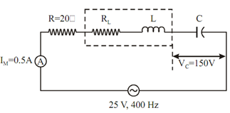
A 20 Ω resistor is connected in series with a coil, a capacitor and an ammeter across a 25 V variable frequency supply. While the frequency is 400 Hz, the current is at its maximum value of 0.5 A and potential difference across the capacitor is 150 V. Determine:

1. Capacitance of capacitor, and

2. Resistance and inductance of coil.

1899_Determine Capacitance of capacitor.png

Figure

Solution

 (a) Let capacitance = C farad

Resonant frequency, f0 = 400 Hz

Capacitive reactance, X C =1 / ωC =   1 / (2π × 400 × C) = (1/800π × C) Ω

Voltage across capacity = Im XC = 150 V

                                         Im = 0.5 A

∴          0.5 / 800π C = 150

    C =   0.5 / (800 ×π × 150)

= 1.3263 × 10- 6 F

or         C = 1.3263 μF

 (b)       Let, RL and L be the resistance and inductance of coil respectively

Current, I m      =          V/ (R + RL)

                    0.5 = 25 / 20 + RL (?Applied voltage V = 25 V)

                        RL = 30 Ω


Related Discussions:- Determine capacitance of capacitor

Transistor, Transistor A transistor is a semiconductor device that is ...

Transistor A transistor is a semiconductor device that is employed to amplify and switch electronic signals. It is made up of a solid piece of semiconductor material, with min

Delay time - power semiconductor devices , Delay time ( t d ) Initiall...

Delay time ( t d ) Initially a thyristor  remains  in forward  blocking  stat when  anode to cathode forward  voltage  is applied  and gate  to cathode circuit is opened. As t

Explain wireless electromagnetic channels, Q. Explain Wireless electromagne...

Q. Explain Wireless electromagnetic channels? Wireless electromagnetic channels are used in wireless communication systems, in which the electromagnetic energy is coupled to th

Execute a pspice program to solve for the node voltages, Q. For the circuit...

Q. For the circuit given in Figure, develop and execute a PSpice program to solve for the node voltages.

Software defined radio and modulation recognition, As we all know the next ...

As we all know the next century demand for wireless technology is expected to be the commercial implementation of Software Defined Radio (SDR) paradigm to improve base station effi

Illustrate inverting operational amplifier, (a) Give the characteristics of...

(a) Give the characteristics of ideal OP-Amp? (b) Illustrate inverting operational amplifier with feedback. get the expression for voltage gain with feedback? Write short not

Give the principle of biasing a fet amplifier, Q. Give the principle of bia...

Q. Give the principle of biasing a FET amplifier. To correctly bias the FET, the gate needs to be negative with respect to the source. Bias is obtained in the following manner:

Schematic diagram of led based system, Q. Schematic Diagram of LED based Sy...

Q. Schematic Diagram of LED based System ? As shown in the two schematic diagrams above, the LEDs in a seven-segment display are not isolated from each other. Rather, eith

Write Your Message!

Captcha
Free Assignment Quote

Assured A++ Grade

Get guaranteed satisfaction & time on delivery in every assignment order you paid with us! We ensure premium quality solution document along with free turntin report!

All rights reserved! Copyrights ©2019-2020 ExpertsMind IT Educational Pvt Ltd