Design combinational-sequential electronic logic gate, Computer Engineering

Assignment Help:

Combinational/Sequential Logic design with Integrated Circuits (Dual in line package)

Car wash concept with the following steps in a Combinational Logic Diagram:

1.    Start Rinse   

2.    Stop Rinse, Start Soap

3.    Start Brush

4.    Stop Soap, Stop Brush

5.    Start rinse

6.    Stop rinse, Start Dry

7.    Stop Dry

A corresponding LED will light-up when the step is reached on during the car wash sequence/run.  Each LED will be on for 5 seconds.  For steps 2, 4, and 6, those LEDs will light for 8 seconds.

Requirements:  Design Combinational/sequential electronic logic diagram with integrated Circuit items depicted an automated Car Wash process.  All of the integrated circuits used thus far in the course have been 74LS00s and 74000s series.

From the diagram I will actually construct the project on a Pencil Box Logic Designer which has an experimental breadboard. Items used in/on the diagram will include some of the following ICs that can be placed on breadboard:

Logic Gates:

AND gate

Exclusive-OR (XOR) gate

Inverter gate

NAND gate

NOR gate

OR gate

TIMER

Half-Adder

Full-Adder

Comparators

Binary Decoders

Binary-to-Decimal Decoders

Multiplexer (MUX)

Demultiplexer (DEMUX)

Latch

S-R Latch

Gated S-R Latch

D Latch

FLIP-FLOPS

D flip-flop

J-K flip-flop

One shot

Counters & Counter logic operations

Shift Registers

Serial In/Serial Out

Serial In/Parallel Out

Note: Some of the items on the list are combinations of several ICs.  Example: Instead of using XOR gate for logic functions on the diagrams, it can also be a combination of 2 x Inverter Gates, 2 x AND Gates, & 1 x OR Gate.

The PencilBox Logic Designer which I'm using has Logic Indicators (8 x LED), CLOCK, Logic 8 x Switches, 2 x PULSERS push buttons.

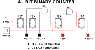
The last diagram I completed was a 4-Bit Counter.  See below:

492_4 bit binary counter.png


Related Discussions:- Design combinational-sequential electronic logic gate

What are latches and flipflops, What are latches and flipflops? There a...

What are latches and flipflops? There are two types of circuits as follows: a. Combinational b. Sequential Flipflops and latches both come into the category of "sequen

Define ufd and mfd, Define UFD and MFD.   In the two-level directory st...

Define UFD and MFD.   In the two-level directory structure, every user has own user file directory (UFD). Every UFD has a same structure, but lists only the files of a single u

Microprocessor, illustration of Z80 instruction set Computer

illustration of Z80 instruction set Computer

Execution of a full instruction - computer architecture, Execution of a ful...

Execution of a full Instruction: Regard as the instruction: Add (R3), R1 Executing this particular instruction needed the below described actions: a) Fetch the

Explain the basic architecture of digital switching systems, Explain the ba...

Explain the basic architecture of digital switching systems. An easy N X N time division space switch is demonstrated in figure. The switch can be shown in an equivalence for

What is set screen, SET SCREEN With SET SCREEN the present screen simpl...

SET SCREEN With SET SCREEN the present screen simply specifies the next screen in the chain , control branches to this next screen  as soon as the current screen has been proce

Define main memory and auxiliary memory, Define main memory and auxiliary m...

Define main memory and auxiliary memory? The memory unit that communicates directly with the cpu is known as main memory [RAM].Devices that give backup storage are known as aux

How to use activex control in .net, How to use ActiveX Control in .Net ? ...

How to use ActiveX Control in .Net ? ActiveX control is a special type of COM component that handles a User Interface. Using ActiveX Control in your .Net Project is even simple

State in brief about virtual memory, What is Virtual memory The term v...

What is Virtual memory The term virtual memory signifies something that appears to be present though actually it is not. Virtual memory technique enables users to use more mem

Explain SR latch using nor gates, Q. Explain SR Latch using NOR gates? ...

Q. Explain SR Latch using NOR gates? Let's inspect the latch more closely.   i. Suppose initially 1 is applied to S leaving R to 0 at this instance. The instant S=1 output o

Write Your Message!

Captcha
Free Assignment Quote

Assured A++ Grade

Get guaranteed satisfaction & time on delivery in every assignment order you paid with us! We ensure premium quality solution document along with free turntin report!

All rights reserved! Copyrights ©2019-2020 ExpertsMind IT Educational Pvt Ltd