Aims
- More practice using data movement and control flow statements.
- Understand techniques to interface microprocessors with external switch-based hardware.
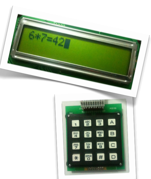
- Write PIC assembly code to implement a simple 1-digit 4-function calculator Equipment
- PIC Trainer and PICkit3 in-circuit debugger PIC trainer numeric keypad
- MPLAB Integrated Development Environment software Background documents (available on FLO)
- MPASM Assembler Users Guide
- PIC18F452 Instruction Set Summary
- PIC Trainer board schematic
Checkpoint 1: Getting Started
1. Obtain a numeric keypad and carefully plug it into Port C of the PIC trainer board, making sure that the board is oriented correctly and the pins are aligned properly with the jacks. Set the DIP switches so that all switches are off except LCD, LEDS C and LEDS D.
2. Create a new MPASM project named prac3, making sure that the processor and toolsuite are correct for the PIC Trainer, the configuration bits are set to the appropriate values, and the correct debugger selected. Create a new project source file named calculator.asm.
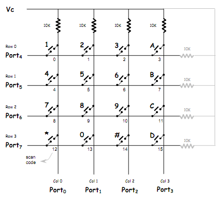
3. The numeric keypad is wired as 4 rows of 4 columns, as shown in the schematic. To operate the device, bits 0-3 of the control port (PORTC in this prac) must be configured as inputs and bits 4-7 must be configured as outputs by writing the appropriate value to TRISC. To read the status of the keypad, a single row output is taken low, and the status of the column inputs is read. If any of the switches on the activated row are pressed, the corresponding column inputs will be pulled low. For example, to see if the 4 key is pressed, set bit 5 low and test bit 0.
4. Write code to initialise the PIC trainer, setting the port D IO bits to output and taking care to set the status of the port C IO bits as appropriate.
5. Write a subroutine named scan_keypad that tests each of the 16 keys on the keypad and returns with a scan code in WREG. The scan code should be the code of the first key found to be pressed, ranging from h'0' for the top-left key (the 1 key) to h'F' for the bottom-right key (the D key). If no key is pressed, the subroutine should return the special value h'FF'. The simplest way to test for a particular key is to write a value to PORTC that has zeroes for the bits corresponding to the row and column you want to test and ones for all other bits. Then you can test if the key is pressed by comparing the value read from the port with the value you wrote to it. (The trick works because reading a value back from a bit configured as output will simply read the value written, whereas writing a value to an input bit is effectively ignored.) For example, to test the B key, write the value b'11010111' (zeros for bits 5 and 3), then read the value back. If the values are the same, then you know that column 3 must be being pulled low by the B key. If not, either key B is not pressed, or some other key is also pressed. An easy way to test all keys is to write a lookup routine that maps a scan code into the appropriate bit pattern for that key, then loop over all of the possible scan codes looking for one that matches. If you get to the end of the loop without finding a match, return the "no key" code instead. 6. Write a main loop that repeatedly calls your scan_keyboard routine and writes the return value to PORTD. When you press a key, the corresponding code should show on the port D LEDs (in binary, of course). When no key is pressed, all of the LEDs should be lit.
Checkpoint 2: ASCII Codes
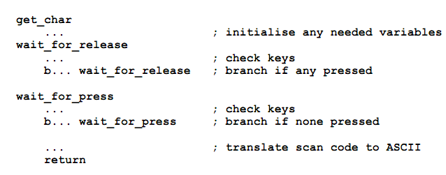
7. Write a subroutine named get_char that reads a single key press from the keypad and returns the key's ASCII code in WREG. To check for a key press event, the routine will first need to wait for any previously pressed keys to be released, then wait for a new key to be pressed. The code will look something like this:
The code to check which keys are pressed should take into account the possibility of switch bounce in the keypad. Otherwise, a "noisy" switch press will appear to the code as several rapid keystrokes. A suitable de-bounce technique is to read the keypad three times in succession with a short delay (10 ms is typical) between each read. If all of the values agree, you can assume that the switch is stable and use the value. But if any value differs, the switch must be "bouncing" so you'll need to go back and begin the sequence again. The simplest way to translate the scan code to ASCII is via yet another lookup table. Since the keypad will be used later in this prac to provide input for a calculator, the appropriate value to return for the number keys is the ASCII code for the digits. The other keys should be mapped as follows:
A ⇒ '+', B ⇒ '-', C ⇒ '*', D ⇒ '/', # ⇒ '=', * ⇒ 'C'.
8. Modify your main loop so that it calls get_char to read ASCII codes from the keypad and displays them on the LCD. Successive values can be displayed by calling the LCD subroutine (from LCD.asm) with the value in WREG. However if the value read is 'C' (for "clear"), the LCD display should be cleared instead. You'll need to include the file LCD.asm and call init_LCD to initialise the LCD module before sending it any output. Checkpoint 3: Single-Digit, Single-Function Counter
9. Modify your main loop so that it implements a single-digit calculator with only one function: addition. Your code should read and display a sequence of 4 key presses, which will consist of a digit key, one of the operator keys (the only one that need work for now is the A or '+' key), another digit key, and the # or '=' key. It should then calculate and display the answer as a 2-digit decimal number. To calculate the sum, you'll first need to convert the ASCII digit codes to the corresponding digit values by subtracting h'30'. Then you can add the digits and adjust for any decimal overflow using the DAW instruction. Finally, you'll need to convert the high and low nibbles of the result back into displayable ASCII codes by adding h'30'. Checkpoint 4: Multi-Function Calculator
10. Extend your calculator to implement the other 3 arithmetic functions. To implement the other functions, you may wish to make use of the following strategies
- Subtraction is best implemented by adding the negative of the second number. To represent a negative number in BCD, use the 10's complement (formed by taking the 9's complement and adding 1).
- Multiplication is best implemented as repeated addition. Initialise a result variable to zero, then use the second number as a loop counter and repeatedly add the first number to the result.
- Division (not that it's particular useful for single-digit operands!) is best implemented as repeated subtraction. Initialise a result variable to zero, then count the number of times you can subtract the second number from the first before the result becomes negative. You'll need to check for the special case where the second number is zero.
To Explore Further
11. (Difficult) Extend the calculator to 2 digits. You can use a 1-byte value (encoded as 2 BCD digits) for the operands and a 2-byte value for the result. You'll probably find it convenient to implement a 2-byte BCD addition routine.
12. (Very challenging) Extend the calculator to multiple digits. The simplest strategy is probably to use one byte per digit, with subroutines to perform the various arithmetic operations.