Describe about boltzmann constant, Electrical Engineering

Assignment Help:

Q. Describe about Boltzmann constant?

The constant η in Figure (b) stands for the noise power spectral density, expressed in terms of power per unit frequency (W/Hz). Statistical theory shows that

η = kT

where k is the Boltzmann constant given by 1.381 × 10⁻²³ J/K and T is the source temperature in kelvins. Equation suggests that a hot resistance is noisier than a cool one, which is compatible with our notion of thermally agitated electrons. At room temperature T0 ≅ 290 K (17° C), η0 works out as 4 × 10-21 W/Hz.

1197_Describe about Boltzmann constant.png

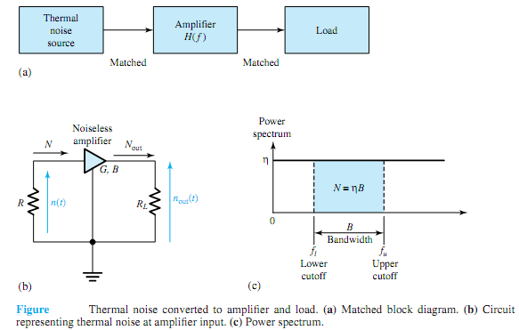
When we employ amplifiers in communication systems to boost the level of a signal, we are also amplifying the noise corrupting the signal. Because any amplifier has some finite passband, we may model an amplifier as a filter with frequency response characteristic H(f). Let us evaluate the effect of the amplifier on an input thermal noise source.

Figure (a), in block diagram form, illustrates a thermal noise source connected to a matched two-port network having frequency response H(f) and the output of the network connected to a matched load. Figure (b) shows a thermal noise source represented by a resistance R connected to an amplifier with a matched input resistance. Presuming the amplifier to be noiseless, with power gain G and bandwidth B, the output noise power is

Nout = GN = GηB

where N = ηB represents the source noise power [the area under the power-spectrum curve falling within the passband, as shown in Figure (c)] accepted by the amplifier as input. The rms noise voltage for a thermal source connected to a matched resistance is then given by

ηrms = √RkTB

The open-circuit voltage would be twice this value.


Related Discussions:- Describe about boltzmann constant

Current flow through the channel of a jfet after pinch off, Q. How does cur...

Q. How does current flow through the channel of a JFET after pinch off? It is seen that above the pinch off voltage at a constant value of VDS (saturation drain current, ID inc

Determine the open-circuit output voltage, Q. Determine the open-circuit ou...

Q. Determine the open-circuit output voltage v o of the system shown in Figure as a function of the input voltage v i .

Explain the purpose of the global descriptor table register, Explain the pu...

Explain the purpose of the global descriptor table register. The GDTR stand for global descriptor table register and IDTR stand for interrupt descriptor table register conta

What is global positioning satellite, What is Global Positioning Satellites...

What is Global Positioning Satellites (GPS) Global positioning satellite (GPS) systems are used to determine exact location of a car, ship, airplane or any conveyance that trav

Role of erc - salient features of nep, Role of ERCs: A National Elect...

Role of ERCs: A National Electricity Policy is one of the key instruments for providing policy guidance to the Electricity Regulatory Commissions in discharge of their functio

Npn bjt with forward-biased, NPN BJT with forward-biased: An NPN trans...

NPN BJT with forward-biased: An NPN transistor can be referred as two diodes along with a shared anode. In common operation, the base-emitter junction is forward biased and th

Fourier deconstruction, Find the Fourier series as far as the third harmoni...

Find the Fourier series as far as the third harmonic, to represent the periodic function y, given by the values in the following table. x 0 o 30

Jfet common source amplifier, Q. JFET Common Source Amplifier? The comm...

Q. JFET Common Source Amplifier? The common source configuration for a FET is similar to the common emitter bipolar transistor configuration, and is shown in figure. The common

What is inter digit time, Q. What is inter digit time? Break time is no...

Q. What is inter digit time? Break time is nominally 61 ms and make time is nominally 39ms. Digits are separated by idle period of 300 ms known as inter digit time. It is vital

Compute current in given the circuit configuration, Q. Consider the circuit...

Q. Consider the circuit configuration shown in Figure. Let V i = 1V, R 1 = 1000, R 2 = 2000, and A = 3. (a) Compute i 2 . (b) If R 1 changed to 500 , recompute i 2 .

Write Your Message!

Captcha
Free Assignment Quote

Assured A++ Grade

Get guaranteed satisfaction & time on delivery in every assignment order you paid with us! We ensure premium quality solution document along with free turntin report!

All rights reserved! Copyrights ©2019-2020 ExpertsMind IT Educational Pvt Ltd