Derive bending equation, Mechanical Engineering

Assignment Help:

Q - Derive bending equation that is,; M/I =  σ /y = E/R.                                                                          

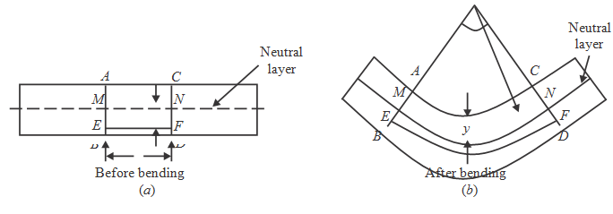
Sol.: With reference to the figure given to us, consider any two normal sections AB and CD of a beam at small distance   δ L apart (that is, AC = BD = δ L). Let AB and CD intersect neutral layer at the points M and N respectively.

Let;

M = bending moment acting on beam

θ = Angle subtended at centre by the arc.

R = Radius of curvature of neutral layer M' N' .

At any distance 'y' from neutral layer MN, consider layer EF.

As shown in the figure the beam because of sagging bending moment. After bending, A' B', C' D' , M' N'  and

E'F' represent final positions of AB, CD, MN and EF in that order.

When produced, A' B' and C' D' intersect each other at the O subtending an angle θ radian at point O, which is centre of curvature.

As   L is quite small, arcs A' C' , M' N' , E' F'  and B' D'  can be taken as circular.

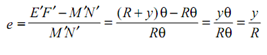
Now, strain in layer EF because of bending can be given by e = (E F  - EF)/EF = (E F  - MN)/MN

As MN is the neutral layer, MN = M' N'


2366_bending equation.png 
Let; σ  = stress set up in layer EF  because of bending

E = Young's modulus of material of beam.
1131_bending equation1.png
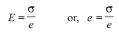
Equate the equation (i) and (ii);
1553_bending equation2.png  


Let;       σ = stress set up in layer EF because of bending

E = Young's modulus of material of beam.

704_bending equation3.png

1134_bending equation4.png

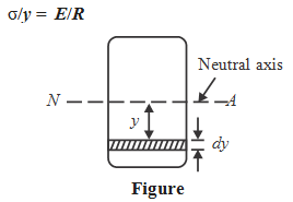
At distance 'y', let us consider an elementary strip of quite small thickness dy. We have already assumed that 'σ ' is bending stress in this strip.

Let dA = area of the elementary strip. Then, force developed in this strip =   σ.dA.

Then the, elementary moment of resistance because of this elementary force can be
given by dM = f.dA.y

Total moment of resistance because of all such elementary forces can be given by
1355_bending equation5.png
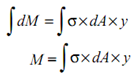
From the Equation (iii),
185_bending equation6.png
By putting this value of  f in Equation (iv), we get
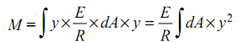
1918_bending equation7.png
But
2036_bending equation8.png
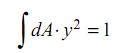
where  I = Moment of inertia of whole area about neutral axis N-A.
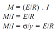
2439_bending equation9.png

Where;

M = Bending moment

I  = Moment of Inertia about axis of bending that is; Ixx

y  = Distance of the layer at which the bending stress is consider

(We take always the maximum value of y, that is, distance of extreme fiber from N.A.)

E = Modulus of elasticity of beam material.

R = Radius of curvature


Related Discussions:- Derive bending equation

Engineering design, 1) State five factors that must be considered when choo...

1) State five factors that must be considered when choosing a material. Discuss the importance to the engineer of each of these factors. 2) An engineer is planning to design a s

Calculate the length of plastic deformation, Calculate the length of plasti...

Calculate the length of plastic deformation: Calculate the length of plastic deformation along 45o in case the applied stress is 63.25% of yield stress in the plate of abov

Determine the efficiency of bell coleman cycle, (a) Derive a mathematical e...

(a) Derive a mathematical expression to determine the efficiency of Bell Coleman Cycle. (b) A dense air refrigeration cycle acts between pressures of 4 bar and 16 bar. The air t

Alloys, hardenability of ferrous and non ferrous alloys

hardenability of ferrous and non ferrous alloys

Objectives of entrepreneurship development , Objectives After studying...

Objectives After studying this unit, you should be able to weigh the merits and demerits of becoming an entrepreneur, discuss the opportunities and financial assis

Equipment for resistance welding-measurements, EQUIPMENT FOR RESISTANCE WEL...

EQUIPMENT FOR RESISTANCE WELDING-Measurements Measurement of the parameters are important while fixing the parameters or testing a machine. Resistance welding instrumentation s

Determine the maximum bending stresses, Evaluate the maximum bending stress...

Evaluate the maximum bending stresses: A beam of I-section illustrated in Figure is simply supported over a span of 10 m. It carries an uniform load of 4 kN/m over the whole s

V-block and clamp - angle projection drawing, A V-block clamp consists of 3...

A V-block clamp consists of 3 components, a V-block, yoke and clamping screw.  Using a rule, measure the sketches below and produce a 3rd angle projection drawing for each componen

Write Your Message!

Captcha
Free Assignment Quote

Assured A++ Grade

Get guaranteed satisfaction & time on delivery in every assignment order you paid with us! We ensure premium quality solution document along with free turntin report!

All rights reserved! Copyrights ©2019-2020 ExpertsMind IT Educational Pvt Ltd