Define lines parameters, Electrical Engineering

Assignment Help:

Define Lines Parameters

In power system analysis, the parameters of interest when modelling power lines are:  inductance, capacitance, series resistance and leakage resistance. A 3-phase line with equilateral spacing of the conductors is shown in Figure. When performing power system studies on 3-phase systems it is usual to use a single-phase equivalent circuit. Therefore, the equivalent 1-phase or line to neutral (hypothetical neutral conductor) equivalent parameters are of interest. It can be shown that the 1-phase equivalent inductance and capacitance of a 3-phase line (assuming D > > r) are given as:

925_Lines Parameters 1.png

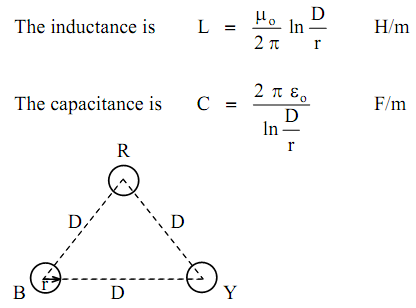
where D  is the distance between the centres of the conductors,

 r  is the radius of the conductors,

  μo = 4 π × 10-7   H/m   is the free space magnetic constant,

  εo = 8.854 × 10⁻¹²  F/m  is the free space electric constant.

It may be of interest to note that  L × C  =  μo × εo

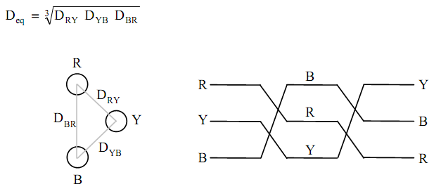
If the conductors are not spaced in the equilateral formation, the flux linkages and hence the inductance of each phase are not the same. It follows that the resultant 3-phase circuit is unbalanced even when the supply voltages and the load currents are balanced. To provide for this problem, the position of the conductors are exchanged at regular intervals along the line, as shown in Figure.

This technique is called 'Transposition'.

In this case, an equivalent spacing between conductors is normally used as:

1103_Lines Parameters.png

The series resistance of the line is the effective a.c. resistance of the conductors which is higher than the d.c. resistance due to skin effect. The leakage resistance represents the combined effect of all various paths from the conductor to earth. It is difficult to assess the value of the leakage resistance due to its dependence on the weather conditions. Normally, its value is very high for most calculation purposes, and the leakage current is negligible.


Related Discussions:- Define lines parameters

Show color television receiver, A color television receiver is shown in Fig...

A color television receiver is shown in Figure in block diagram form, indicating only the basic functions. The early part forms a straightforward superheterodyne receiver, except f

Determine vout and the power supplied, Q. An operational amplifier stage is...

Q. An operational amplifier stage is typically represented by the circuit of Figure. For the values given, determine V out and the power supplied by the 2.5-V source.

When mt2 is negative and g is positive , When MT 2 is Negative  and g is ...

When MT 2 is Negative  and g is positive In this  case  gate  current  flows  through  junctions P 2 N 2   electrons  are injected from  N 2   layer to  P 2   a result  junct

Analysis of frequency response with pspice and probe, Analysis of Frequency...

Analysis of Frequency Response with PSpice and PROBE PSpice can readily accomplish the circuit analysis as a function of frequency, and PROBE can display Bode plots for magnitu

Transformers, What is the difference between “Insulating,” “Isolating,” and...

What is the difference between “Insulating,” “Isolating,” and “Shielded Winding” transformers? Can Acme Transformers be reverse connected? . Can Transformers develop Three Phase po

What is extended memory system, What is XMS? XMS: The memory system is ...

What is XMS? XMS: The memory system is splits in three major parts as: system area, XMS (extended memory system) and TPA (transient program area). The kind of microprocessor in

EMI, Ask question (c) Reduce each of the given signal transmission situatio...

Ask question (c) Reduce each of the given signal transmission situations to a source, coupling path(s), and receptor: (i) AM radio transmission to the human ear. (ii) TV transmis

Explain the limiting the spectrum, Explain the Limiting the Spectrum Th...

Explain the Limiting the Spectrum This low-pass filter is known an anti-aliasing filter. These filters are originated at the input to most applications. Since they are required

Draw the block diagram of phase cancellation ssb generator, a. The antenna ...

a. The antenna current of an AM broadcast transmitter, modulated to depth of 40% by an audio sine wave is 11 amp. It enhances to 12 amp as a result of simultaneous modulation by an

Dc basing bits, Dc basing bits: Operating point: operating is cut off...

Dc basing bits: Operating point: operating is cut off; saturation and linear region of bits character are provided as follow: (1)  Linear-region operation (2)  (1)

Write Your Message!

Captcha
Free Assignment Quote

Assured A++ Grade

Get guaranteed satisfaction & time on delivery in every assignment order you paid with us! We ensure premium quality solution document along with free turntin report!

All rights reserved! Copyrights ©2019-2020 ExpertsMind IT Educational Pvt Ltd