Construct of a diagonal scale, Mechanical Engineering

Assignment Help:

Construct of a diagonal scale:

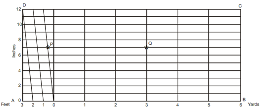
During construct of a diagonal scale of RF = 1/48, displaying yards, inches and feet to represent a maximum length of 7 yards. Scratch a distance of 7 inches and 3 yards on this scale.

Solution

(a)   Acquire the length,

 L = 1 × 7 × 36 inches/48

= 5.25 inches

 (b) Scratch a line AB, 5.25 inches long, and divide it into seven equivalent parts to display yards.

(c) Scratch the first part into three equivalent divisions.

(d) Scratch 12 equidistant or about 3 millimeter apart parallel lines above AB and make the rectangle ABCD. Join D-2 and scratch parallel via 0, 1 and 2.

Distance PQ represents the length 7 inches and 3 yards.
 

2337_Construct of a diagonal scale.png

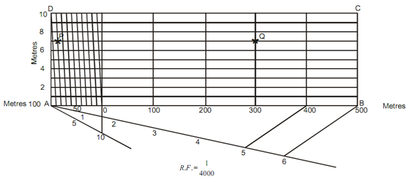
During construct of a diagonal scale of RF = 1/4000 to signify meters (m) and long sufficient to measure 600 meters (m). Mark a distance of 387 meters (m) on this scale.

Solution

(a)   Length of the scale = (1/4000) *× 600 × 100 centimeter

                                          = 15 centimeter

(b) Sketch a line AB 15 centimeter long and divide it into six equivalent parts to represent hectometers.

 (c)Divide the first part into ten equivalent parts to represent decameters (dm).
2189_Construct of a diagonal scale1.png

(d) Sketch ten equidistant or 3 millimeter apart parallel lines above AB and make the rectangle ABCD. Join the first sub-division in the direction of the left from the zero on the line AB, to the second division on the top or 10th line, hence completing the diagonals. On these diagonals, the least count is 10/10 = 1 meter (m).

PQ signifies the distance of 387 meters (m).


Related Discussions:- Construct of a diagonal scale

Joint details and preparations, Joint Details and Preparations Joints s...

Joint Details and Preparations Joints shall be prepared by machining, flame cutting with grinding to bright metal or air-carbon arc gouging with grinding to bright metal such t

Relation between intensity bending moment and shear force, Relation between...

Relation between intensity bending moment and shear force: What is the relation between load intensity bending moment and shear force Consider the beam subjected to any t

Vectors, Following sets of the three forces act on a body,. In which case r...

Following sets of the three forces act on a body,. In which case resultant cannot be zero? 1) 10N, 10N, 10N 2)10N, 10N, 20N 3)10N, 20N, 20N 4010N, 20N, 40N Ans)      In 4th

Thermodynamics, Q2 A 3kW electric water heater is a cylindrical element hav...

Q2 A 3kW electric water heater is a cylindrical element having outside diameter 10mm. The heat transfer between the heater and the surrounding water is 980W/m2K. Determine the leng

Calculate machining time and material removal rate, Calculate Machining Tim...

Calculate Machining Time and Material Removal Rate A hole of 40 mm diameter and 50 mm depth is to be drilled in a mild steel component. The cutting speed can be taken as 65 m/

Assignment, AskTask 2 (3 questions) Material engineers should be conversant...

AskTask 2 (3 questions) Material engineers should be conversant of various materials, their properties, manufacturing process involved, environmental issues, monetary issues and mo

Bench vices tool and equipment , Bench Vices: Bench vice is used to hold a...

Bench Vices: Bench vice is used to hold a job on a bench. It consists of a movable jaw, a fixed jaw, spindle and a lever. Figure shows a bench vice. The movable jaw is in the fron

Generation of steam at constant pressure - thermodynamics, Generation of st...

Generation of steam at constant pressure: Steam is pure substance. Like any other pure substance it can also be converted into any of the three states, that is, solid, liquid

Orthographic projections, Orthographic Projections: As you learned pre...

Orthographic Projections: As you learned previously about the theory of projection of points, planes and lines, the next significant is the projection of solids that have thre

determine the minimum cross section area of graph, To design a cantilevere...

To design a cantilevered truss to support the loads shown in the figures, two layouts are proposed as shown in Figs. A and B. All truss members are steel with allowable stress of 2

Write Your Message!

Captcha
Free Assignment Quote

Assured A++ Grade

Get guaranteed satisfaction & time on delivery in every assignment order you paid with us! We ensure premium quality solution document along with free turntin report!

All rights reserved! Copyrights ©2019-2020 ExpertsMind IT Educational Pvt Ltd