COMPUTER INPUT:
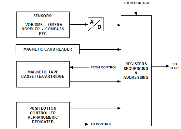
Figure shows input information for a typical airborne digital computer.

The sensors in Figure develop analogue electrical signals representing: -
- Bearing and distance to fixed point (VOR/DME).
- Hyperbolic co-ordinates (Omega).
- Ground speed and drift angle (Doppler).
- Aircraft heading (Compass), etc.
These analogue signals must be converted into digital signals before being fed to the computer memory. ADCs, which may be an integral part of the sensor equipment achieve this, or alternatively a converter unit may be installed, which carries out all necessary analogue to digital conversion.
Computer Output
Many different kinds of output device are used, including traditional devices such as relative bearing indicators and steering indicators. With these, suitably designed digital to analogue converters must be used. Similar outputs could be fed to an autopilot.
Digital read out can be obtained by use of hybrid (digital and analogue) servo systems, which position an output counter drum or alternatively by use of 7 segment indicators. A ROM, which has the wired in program to convert from binary code to the appropriate drive, drives the segments, which may be light emitting diodes (LED) or liquid crystals (LCD).
Cathode ray tubes (CRT) are being increasingly used as output devices both for display of alphanumeric information and, less commonly, electronic maps. CRTs are essentially analogue devices and as such require DACs, which will provide the necessary fairly, complicated drives.
Moving map displays may also be used as a means of presenting navigation information to the pilot. The map itself may be an actual chart fitted on rollers, or alternatively projected film. Closed loop servos, which drive the map, are fed from the computer via DACs.