Computer-aided circuit analysis using MATLAB, Electrical Engineering

Assignment Help:

Q. Computer-aided circuit analysis using MATLAB ?

This text does not teach MATLAB; it assumes that the student is familiar with it through previous work. Also, the book does not depend on a student having MATLAB. MATLAB, however, provides an enhancement to the learning experience if it is available. If it is not, the problems involving MATLAB can simply be skipped, and the remainder of the text still makes sense.If one wants to get a quick introduction, the book entitled Getting Started with MATLAB 5 by R. Pratap, listed under Selected Bibliography for Supplemental Reading for Computer-Aided Circuit Analysis, may be a good source.

1342_Computer-aided circuit analysis using MATLAB.png

MATLAB (MATrix LABoratory), a product of The MathWorks, Inc., is a software package for high-performance numerical computation and visualization. It is simple, powerful, and for most purposes quite fast with its easy-to-learn and easy-to-use language. It provides an interactive environment with hundreds of built-in functions for technical computation, graphics, and animation. MATLAB also provides easy extensibility with its own high-level programming language.

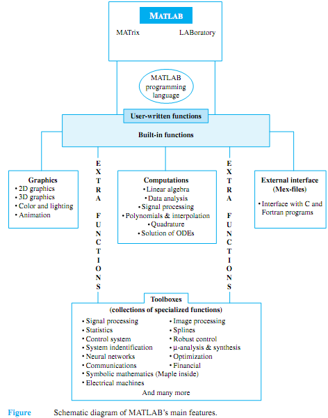
Figure illustrates MATLAB's main features. The built-in functions with their state-of- the-art algorithms provide excellent tools for linear algebra computations, data analysis, signal processing, optimization, numerical solution of ordinary differential equations (ODE), numerical integration (Quadrature), and many other types of scientific and engineering computations. Numerous functions are also available for 2D and 3D graphics as well as for animation. Users can also write their own functions, which then behave just like the built-in functions. MATLAB even provides an external interface to run Fortran and C programs. Optional "toolboxes," which are collections of specialized functions for particular  applications, are also available. For example, the author of this text has developed "Electrical Machines Toolbox" for the analysis and design of electrical machines.


Related Discussions:- Computer-aided circuit analysis using MATLAB

Working of self - excited generators, Q. Working of self - excited generato...

Q. Working of self - excited generators? For self-excited generators, residual magnetism must be present in the ferromagnetic circuit of the machine in order to start the self-

Sinusoidal inverter, i am going to make a sinusoidal inverter as my final y...

i am going to make a sinusoidal inverter as my final year project kindly help me in this regard.How can i make this project?

Combinational-sequential, Design combinational-sequential electronic logic ...

Design combinational-sequential electronic logic gate circuit for a car wash....

Determine the electromagnetic force on the plunger, Q. Consider the electro...

Q. Consider the electromagnetic plunger shown in Figure. The λ-i relationship for the normal working range is experimentally found to be λ = Ki 2/3 /(x+t), where K is a constant. D

Circuit, y more number of resistance and capacitor are used in a circuit w...

y more number of resistance and capacitor are used in a circuit what is the purpose to add ore than one..?

Programming, ELEC 132 COURSEWORK – ADC This work will be assessed based...

ELEC 132 COURSEWORK – ADC This work will be assessed based on program demonstration (during lab sessions) and design. You will also have to submit your c-source codes as word o

Voltage regulator, Voltage regulator: A voltage regulator is an electr...

Voltage regulator: A voltage regulator is an electrical regulator intended to automatically keep a constant voltage level. A voltage regulator is an instance of a negative fee

For the nor and inverter realizations, Q. For the NOR and inverter realizat...

Q. For the NOR and inverter realizations shown in Figure, find the truth table, the type of gate realized, and the expression for the logic output, in each case.

Find the largest current out, Q. Consider a BJT switch connected to the nex...

Q. Consider a BJT switch connected to the next stage, as shown in Figure, in which iout is likely to be negative when v out is high. Assume V CC = 5 V, R C = 1k, and the high r

Develop a block diagram for a two-port network, Q. The equations for a two-...

Q. The equations for a two-port network are given by V 1 = z 11 I 1 + z 12 I 2 0 = z 21 I 1 + (z 22 + Z L )I 2 V 2 = - I 2 Z L (a) Satisfying the equations, dev

Write Your Message!

Captcha
Free Assignment Quote

Assured A++ Grade

Get guaranteed satisfaction & time on delivery in every assignment order you paid with us! We ensure premium quality solution document along with free turntin report!

All rights reserved! Copyrights ©2019-2020 ExpertsMind IT Educational Pvt Ltd