Computer added design, Mechanical Engineering

Assignment Help:

Computer added design

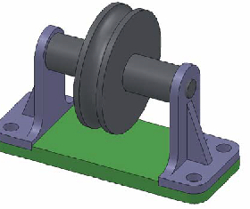
Using SolidWorks create an assembly model of the roller, bracket and base shown to the right. The assembly is also shown in exploded view below. You may choose whatever dimensions (to the nearest mm) you like, except for the distance between hole centres for the brackets, as long as it looks similar to the model shown here. The dimension for the hole centres is based on the alpha numeric value (A=1, Z=26) of the initial of your surname. The hole centre distance should be

√i ×100 (rounded to the nearest 10 mm) where

i is the alpha numeric value of your initial. E.g. if your surname is Brown, the dimension between hole centres will be √2 ×100 × 141 =>140mm. Your part models must capture the correct design intent, i.e. symmetry of parts, axial alignment of cylindrical parts, axle hole concentric with bracket top round. For example, if I change a dimension of one of your parts, the width of the bracket say, I should not have to change any other dimension to restore symmetry to the part. If your model does not do this it will lose marks.

2485_domble.png

Your assembly model should be properly constrained by using appropriate mates. I should be able to change a dimension, the height of the base say, and the rest of the parts should move to the correct locations without further manipulation (except perhaps to "Rebuild" the model). You do not need to have the dimensions of the individual parts dependent on each other although you may do this if you wish/can. For example, if you change the width of the base, it is not necessary (for the purposes of the assignment) to have the width of the bracket automatically update to match it.

Create the following drawings from your solid and assembly models:

1. three orthographic views and an isometric view showing of the bracket part. The orthographic views should be properly dimensioned following the guidelines discussed in lectures.

2. an isometric assembly drawing and an exploded assembly drawing of the Roller assembly. This drawing should also contain a Bill of Materials.

If you work together with others you must create your own models and ensure that your dimensions are different from theirs. Any two or more submissions that have identical dimensions will be considered to be copied and will receive no marks.


Related Discussions:- Computer added design

Wedge friction, WEDG E FRICTION: Explain how wedge is used for raisi...

WEDG E FRICTION: Explain how wedge is used for raising heavy loads. Also give principle of it. Sol.: Principle of wedge: A wedge is small piece of material having two

Explain gear forming, Explain Gear Forming In gear form cutting, cuttin...

Explain Gear Forming In gear form cutting, cutting edge of the cutting tool has a shape similar with the shape of the space among the gear teeth. Two machining operations, mill

Authoe, can i ask who the author of this website is?

can i ask who the author of this website is?

Vendor drawing and data review, The Mechanical Engineer/Specialist shall be...

The Mechanical Engineer/Specialist shall be responsible for specifying Vendor Drawings and Data Requirements in the MRQ and MRP using the WorleyParsons standard vendor drawing and

Wrought aluminium alloys, Wrought Aluminium Alloys Extrusion ingots an...

Wrought Aluminium Alloys Extrusion ingots and sheets are cast through semi-continuous direct chill method. The sheet ingots are scalped in which about 12 millimeter of ingot s

Explain fundamental of metal casting, Q. Explain Fundamental of metal casti...

Q. Explain Fundamental of metal casting? (1)Melting the material (2)Allowing the molten metal to cool and solidify in the mould "A plane where the castings are made is ca

Types of holons, Types of Holons The four major types of holons are: ...

Types of Holons The four major types of holons are: Order holons Product holons Resource holons Staff holons Considering the cooperative aspect of the

Determine the production rate, a) You were assigned to determine the produc...

a) You were assigned to determine the production rate for a polymer extrusion process. The extruder is found to have a barrel diameter = 4.5 in and length = 11 ft. The extruder scr

Write Your Message!

Captcha
Free Assignment Quote

Assured A++ Grade

Get guaranteed satisfaction & time on delivery in every assignment order you paid with us! We ensure premium quality solution document along with free turntin report!

All rights reserved! Copyrights ©2019-2020 ExpertsMind IT Educational Pvt Ltd