Compute the total capacitance with parallel connection, Electrical Engineering

Assignment Help:

Compute the total capacitance with parallel connection:

Three capacitors C1, C2 and C3 contain capacitance 20 μf, 15 μf, 30 μf, respectively. compute:

1. Charge on each of the capacitor when connected in parallel with 220 V supply.

2. Total capacitance with parallel connection.

3. Voltage across each of the capacitor when connected in series and 220 V supply is given to this series connection.

Solution

 (a) Capacitors are in parallel:
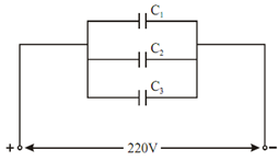
2228_Compute the total capacitance with parallel connection.png

Figure

Q1 = C1 V = 20 × 10-6  × 220 = 4400 × 10

Q2 = C2 V = 15 × 10- 6 × 220 = 3300 × 10- 6 C

Q3  = C3 V = 30 × 10- 6 × 220 = 6600 × 10- 6  C

 (b)       Total capacitance :

      C = C1 + C2 + C3

          = (20 + 15 + 30) × 10- 6

           = 65 μF

(c) As capacitors are in series so charge Q remains same for all capacitors.
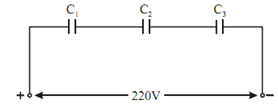
 

1365_Compute the total capacitance with parallel connection1.png

Figure

1 /Ceq      =  (1 / C1 )+   (1 / C2 ) +(1/C3)

1 / Ceq =   1 /20  + 1/15 + 1/30  = 0.05 + 0.0666 + 0.0333

 Ceq = 6.667 μF

Total charge Q = Ceq × V

= 1466.74 μC

Now,    Voltage across C1 is V1 = Q/ C1 = 73.337 volt

Voltage across C  is V   =  Q/ C2 == 97.78 volt

Voltage across C  is V  =  Q/C3  == 48.89 volt


Related Discussions:- Compute the total capacitance with parallel connection

Purpose of control word written to control register in 8255, What is the pu...

What is the purpose of control word written to control register in 8255? The control words written to control register state an I/O function for every I.O port. The bit D7 of t

Explain standard set of procedure used in completing a call, Q. Explain Sta...

Q. Explain Standard set of procedure used in Completing a call? Completing a local telephone call between two subscribers linked to the same telephone switch is accomplished th

Communication systems/theory, have 18 multiple choice questions i need answ...

have 18 multiple choice questions i need answered by 9am cst and will pay Need ASAP

Illustrates typical thermal noise waveform, Q. Illustrates typical thermal ...

Q. Illustrates typical thermal noise waveform? In general, any physical resistor or lossy device can be modeled by a noise source in series with a noiseless resistor, as shown

Find the power supplied by the voltage source, Find the power supplied by t...

Find the power supplied by the voltage source and the power absorbed by the 24 Ω resistor (R3) in the circuit shown below:   Determine the voltage V2 in the circuit shown.

Critical rate of rise of voltage - thyristor , Critical Rate of Rise of Vol...

Critical Rate of Rise of Voltage It  depends on  the junction temperature higher  the junction  temperature lower  the critical rate of  rise of  voltage. It is also known  as

Find the input resistance and output resistance, Quite often an amplifier i...

Quite often an amplifier is used as a component of an amplifier circuit. Consider the amplifier circuit shown in Figure, which contains an amplifier block as an internal component.

Single phase full wave mid point type rectifier , Single Phase Full Wave M...

Single Phase Full Wave Mid Point Type  Rectifier A single  phase full wave  mid point  type controlled  rectifier consists  two  thyristors  one centre tapped  transformer  an

Draw a block diagramfor a 2-to-4 decoder, Q. Draw a block diagramfor a 2-to...

Q. Draw a block diagramfor a 2-to-4 decoder. Obtain the truth table, and develop a logic diagram.

Write Your Message!

Captcha
Free Assignment Quote

Assured A++ Grade

Get guaranteed satisfaction & time on delivery in every assignment order you paid with us! We ensure premium quality solution document along with free turntin report!

All rights reserved! Copyrights ©2019-2020 ExpertsMind IT Educational Pvt Ltd