Compute the maximum bending moment, Mechanical Engineering

Assignment Help:

Compute the maximum bending moment:

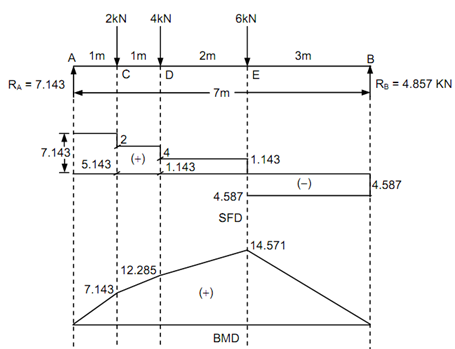
A simply supported beam of 7 m length carries point loads 2 kN, 4 kN and 6 kN at distances of 1 m, 2 m & 4 m from the fixed end respectively. Draw BMD & SFD and also compute the maximum bending moment that will take place.

Solution

By taking moments around A to find RB,

RB × 7 - (6 × 4) - (4 × 2) - (2 × 1) = 0

Therefore,        RB = 4.857 kN, and

RA = 12 - 4.857 = 7.143 kN

Shear Force (Starting from left end A)

 SF at A, FA = + 7.143 kN

SF just left of C = + 7.143 kN

SF just right of C = + 7.143 - 2 = + 5.143 kN

SF just left of D = + 5.143 kN

SF just right of D = + 5.143 - 4 = + 1.143 kN

SF just left of E = + 1.143 kN

SF just right of E = + 1.143 - 6 = - 4.857 kN

SF just left of E = - 4.857 kN = Reaction at B

Bending Moment (Starting from right end B) BM at A, MA = 0

BM at E, ME = + 4.857 × 3 = + 14.571 kN m

BM at D, MD = + (4.857 × 5) - (6 × 2) = + 12.285 kN m

BM at C, MC  = + (4.857 × 6) - (6 × 3) - (4 × 1) = + 7.142 kN m

Or        MC = 7.143 × 1 = + 7.143 kN m   (considering left side)

BM at A,  MA = 0

658_Compute the maximum bending moment.png

Figure

Maximum bending moment shall occur at a point where the shear force changes sign. Here, SF alters from positive to negative at E. The Bending Moment at E shall be maximum bending moment.

Thus,   Mmax = + 14.571 kN m


Related Discussions:- Compute the maximum bending moment

Constructional details of two stroke engine, Constructiona l Details of Tw...

Constructiona l Details of Two Stroke Engine: The basic components are cylinder, piston, piston liners, connecting rod, piston rings, crank pin, crank shaft, counter weight e

Design requirements, A steel member supported by a tie bar has a load of 15...

A steel member supported by a tie bar has a load of 15 000 lbs on it. If the force on the steel member of 1.2 in 2 cross section is 14,180 lbs and the force on the tie bar of diam

Implementation of material requirement planning, Implementation of Material...

Implementation of Material Requirement Planning: The total requirements for a material from an MRP schedule are given in the following table :

Ease of operation-factors in clutch design , Ease of Operation : For highe...

Ease of Operation : For higher power transmissions, the operation of disengaging the clutch must not be tiresome to the driver.

Lap-type flange-to-shell clearance, Q. Lap-Type Flange-To-Shell Clearance? ...

Q. Lap-Type Flange-To-Shell Clearance? Lap-Type Flange-To-Shell Clearance The difference between the flange ID and the shell OD shall not exceed: • 1/16 in (1.6 mm) for n

Illustrate vacancy defect and screw dislocation, Illustrate vacancy defect ...

Illustrate vacancy defect and screw dislocation with diagram. Also show the induced nature of stress and stress by mean of diagram. Illustrate interstitial defect and edge disl

Discover the increase in pressure, Discover the increase in pressure: ...

Discover the increase in pressure: A copper tube of 50 mm diameter and 1200 mm length contains a thickness of 1.2 mm along closed ends. This is filled with water at atmospheri

Tungsten inclusions, Tungsten Inclusions Tungsten inclusion is a disconti...

Tungsten Inclusions Tungsten inclusion is a discontinuity found only in TIG welding. Particles of tungsten from the electrode can be embedded in a weld when improper welding proc

Uniform alternate electric field, Uniform Alternate Electric Field Supp...

Uniform Alternate Electric Field Suppose a particle moves under a uniform (i.e. independent of space co-ordinates) but alternating electric field  E  given by, E = E 0  si

Write Your Message!

Captcha
Free Assignment Quote

Assured A++ Grade

Get guaranteed satisfaction & time on delivery in every assignment order you paid with us! We ensure premium quality solution document along with free turntin report!

All rights reserved! Copyrights ©2019-2020 ExpertsMind IT Educational Pvt Ltd