Compute depth of yielding in the hollow shaft, Mechanical Engineering

Assignment Help:

Compute depth of yielding in the hollow shaft:

A solid shaft 80 mm diameter is solid for a certain length from one end but hollow for the remaining length along inner diameter of 40 mm. If a pure torsion is applied such that yielding occur at the surface of the solid part of the shaft. Compute:

 (1) the depth of yielding in the hollow shaft, and

 (2) the ratio of the angles of twist per unit length.

Solution

τ = Shear stress at yield point.

Torsion in the solid shaft =τ × ( π× 803 /16)

T1 =τ × (π× 803 /16)            ------------- (1)

 For Hollow Shaft

Torsion in the unyielded part

T2 =τ × (π/16 D) (D 4 - 404)                    ----------- (2)

where D = diameter of the hollow section at which yielding begins.

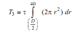
Torsion in yielded part

= (πτ /12 )(803  - D3 ) --------------  (3)

         T1  = T2  + T3

⇒ 803/16 = D4  - 404/16 D +  (803 - D3/12)

⇒         12 × 803 D = ( D4  - 404 ) 12 + 16 D (803  - D3 )

⇒         6144 × 103 D = 12D4  - 3072 × 104  + 8192 × 103 D - 16 D4

⇒         4D4  - 2048 × 103 D + 3072 × 104  = 0

⇒         D 4  - 512 × 103 D + 768 × 104  = 0           ----------- (4)

2411_Compute depth of yielding in the hollow shaft.png

By trial and error, D = 74.8 mm

T / J =  τ/ R = G θ/ l

⇒         θ=  τl /GR                                 ---------- (5)

θS  =2τl / (G × 80)            ------ (6)

θH  = 2τl / (G × D)           --------- (7)

θH/ θS  = 80/ D =   80/74.5 = 1.07


Related Discussions:- Compute depth of yielding in the hollow shaft

Steam turbine types, Is bleed necessary in condensing and back pressure bot...

Is bleed necessary in condensing and back pressure both the turbine? What is the use of bleed in steam turbine? What is the basic difference in condensing and backpressure turb

QFD chart and engineering specifications, Deliverables: A QFD chart, sh...

Deliverables: A QFD chart, showing the relationships between the customer requirements and the engineering specifications. (Refer to the Ullman QFD chart posted on My

Steps for solving problem for finding power, STEP S FOR SOLVING PROBLEM FO...

STEP S FOR SOLVING PROBLEM FOR FINDING POWER: 1. Use formula stress (s) = force (Maximum Tension)/Area Where; Area = b.t that is, Tmax = σ.b.t 2. Unit mass (m) = r.b.t.

Jigs and fixtures, state the purpose and function of work holder

state the purpose and function of work holder

Determine ratio between mass flow rate to condensing steam, Determine ratio...

Determine ratio between mass flow rate to condensing steam: In steam power plant, the steam 0.1 bar and 0.95 dry enters condenser and leaves as saturated liquid at 0.1 bar an

Industrial applications of ultrasonics, Industrial applications of ultraso...

Industrial applications of ultrasonics-cleaning, welding, soldering, drilling

Determine the force, Determine the force: Determine the force P needed...

Determine the force: Determine the force P needed to start block B illustrated in Figure moving to the right if the coefficient of friction is 0.3 for all surfaces of contact.

Strain, is strain in bending important parameter to consider?

is strain in bending important parameter to consider?

Calculate a quarterly delivery schedule, Gibson Ltd operates sportswear sto...

Gibson Ltd operates sportswear stores in Dublin and Cork and has set the following quarterly sales target for international and provlncial rugby shirts for 2013 per the attached sc

Conceptual engineering phase in project development, Q. Conceptual engineer...

Q. Conceptual engineering phase? During this phase, a conceptual engineering estimate will be prepared by Project Management with input from all disciplines. Activities at t

Write Your Message!

Captcha
Free Assignment Quote

Assured A++ Grade

Get guaranteed satisfaction & time on delivery in every assignment order you paid with us! We ensure premium quality solution document along with free turntin report!

All rights reserved! Copyrights ©2019-2020 ExpertsMind IT Educational Pvt Ltd