Common Principles of Ray Tracing
Based upon the nature or attributes of the surface given by the user, the subsequent effects are implemented, as per to rules of optics:
a) Reflection (as per to the angle of incidence and reflectivity of the surface).
b) Refraction (as per to the angle of incidence and refraction index).
c) Display of renderings that is texture or pattern as given, or shadows i.e. on the next nearest object or background concerning transparency or opacity, like the case may be.

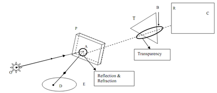
Figure demonstrates some of the common principles of ray tracing.
A ray start from O hits the transparent glass plate P at an angle i.e. A. Then it gets refracted in the plate specified by the kink inside the plate thickness. The exiting ray occurs to hit the edge of the triangle i.e. 'T' and casts a shadow upon the opaque rectangular plate i.e. 'R' at the point C. A portion of the ray incident on the plate P gets reflected at 'A' and the reflected ray hits the elliptical object 'E' at the point 'D'. If P is a green glass plate, the exiting ray AC will be allocated the suitable green colour. If R or E has a textured surface, the consequent point C or D will be specified the attributes of the surface rendering.
If O is a point source of light, the ray OC will position the shadow of the point B upon the edge of the triangle T on the point C at the rectangle 'R'. Diverse locations of light sources may be combined along with be different view positions to enhance the realism of the scene. The way is common also in the sense which it can apply to curved surfaces and also to solids made of flat polygonal segments. Due to its versatile and wide applicability, this is a "brute force" method, concerning massive computer resources and great computer effort.