Every input line of combinational circuit represents a specific element of the string let's say xi and every output line results in the form of a sorted list. In order to get the above mentioned task a comparator is used for the processing.
Every comparator has two input lines suppose a and b, and likewise two output lines say c and d. Every comparator offers two outputs it implies that c provides maximum of a and b (max (a, b)) and d offers minimum of a and b (min (a, b)) in comparator InC and DeC it is opposite as displayed in Figures.
In broad there are 2 types of comparators generally known as increasing comparators and decreasing comparators signified by + BM(n) and - BM(n) where n signifies the number of input lines and output lines of the comparator. The depth of + BM (n) and - BM (n) is log n. These comparators are used for constructing the circuit of sorting.
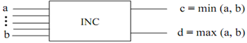
Figure: Increasing Comparator, for 2 inputs
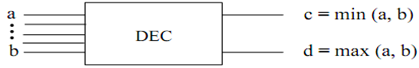
Figure: Decreasing Comparator, for 2 inputs
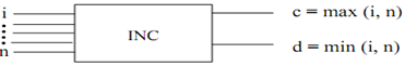
Figure: Increasing Comparator, for n inputs
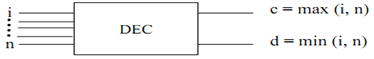
Figure: Decreasing Comparator, for n inputs
Now let's suppose a famous sequence called bitonic sequence and sort out the elements employing a combinational circuit comprising a set of comparators. The property of bitonic sequence is in this manner:
Consider a sequence X= x0, x1, x2, x3, x4 ......xn-1 such that state/condition 1: either x0, x1, x2, x3, x4 .......... xi is a monotonically increasing sequence and xi+1, xi+2, ................ xn-1 is a monotonically decreasing sequence or state 2: there exists a cyclic shift of sequence x0, x1, x2, x3, x4 ................... xn-1 such that resulting sequence satisfies the state 1.
Let's take a few illustrations of bitonic sequence:
B1= 4,7,8,9,11,6,3,2,1 is bitonic sequence
B2= 12,15,17,18,19,11,8,7,6,4,5 is bitonic sequence
In order to give a solution to such a bitonic sequence different stages of comparators are needed. The fundamental approach followed for solving such a problem is as given:
Let's say we have a bitonic sequence X= x0, x1, x2, x3, x4 .......... xn-1 with the property that first n/2 elements are monotonically increasing elements are monotonically increasing such that x0< x1< x2< x3< x4...n/2-1 and other numbers are monotonically decreasing like xn/2> xn/2+1> ...>xn-1. Afterwards these patterns are weighed against with the help of a comparator in this manner:
Y= min(x0, xn/2), min(x1, xn/2+1), min(x2, xn/2+2), ...........Min (xn/2-1, xn-1)
Z= max(x0, xn/2), max (x1, xn/2+1), max (x2, xn/2+2), ........Max (xn/2-1, xn-1)
After the above considered iteration, the two new bitonic sequences are generated and the method is known as bitonic split. Thenafter a recursive operation on these two bitonic sequences is processed until we are able to achieve the sorted list of elements. The accurate algorithm for sorting the bitonic sequence is as follows:
Sort_Bitonic (X)
// Input: N Numbers following the bitonic property
// Output: Sorted List of numbers
1) The Sequence which means that X is transmitted on the input lines of combinational circuit that consists of different set of comparators.
2) The sequence X is divided into two sub-bitonic sequences let's say Y and Z with the help of a process called bitonic split.
3) Recursively executes the bitonic divide on sub sequences which means that Y and Z till the size of subsequence reach to a level of 1.
4) The sorted sequence is attained after this phase on the output lines.