Collector-to-base bias, Electrical Engineering

Assignment Help:

Collector-to-base bias:

620_Collector-to-base bias.png

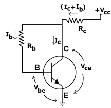
Figure: Collector-to-base bias

This configuration uses negative feedback to avoid thermal runaway and stabilize the operating point. In this category of biasing, the base resistor RB is associated to the collector in place of connecting it to the DC source Vcc. Thus any thermal runaway will induce a voltage drop across the RC resistor which will throttle the transistor's base current.

From voltage law of Kirchhoff, the voltage VRb across the base resistor Rb is

199_Collector-to-base bias1.png

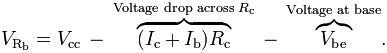
By the Ebers-Moll model, Ic = βIb, and thus:

1764_Collector-to-base bias2.png

From law of Ohm, the base current Ib = VRb/Rb, and thus

398_Collector-to-base bias3.png

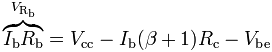
Therefore, the base current Ib is

Ib = Vcc - Vbe/ (Rb+ (β+1) RC)

If Vbe is held stable and temperature get increases, after that the collector current Ic increases. Though, a larger Ic causes the voltage drop across resistor Rc to increase that in turn decreases the voltage VRb across the base resistor Rb. A lower base-resistor voltage drop decreases the base current Ib that results in less collector current Ic. Since an increase in collector current with temperature is opposed, the operating point is reserved stable.


Related Discussions:- Collector-to-base bias

Communication network, Assuming that the receiver sends a XOFF signal when ...

Assuming that the receiver sends a XOFF signal when the receive buffer is P% full in order to avoid any data or packet loss.

Find the parameter values for channel mosfet, Q. Find the parameter values ...

Q. Find the parameter values V T and I DSS for a p- channel MOSFET with i D = 0 when v GS ≤-3 V, and i D = 5 mA when v GS = v DS =-8V.You may neglect the effect of v DS on

Field effect transistors, basic configuration of field effect transistors i...

basic configuration of field effect transistors in mplifiers

Illustrate the experts model of GPS system, Illustrate the experts model of...

Illustrate the experts model of GPS System A fundamental expert system is made up of the below elements: Setting up an Expert System -  Information is collected

Determine the percentage reduction in the applied voltage, A large inductio...

A large induction motor is usually started by applying a reduced voltage across themotor; such a voltage may be obtained from an autotrans- former. A motor is to be started on 50%

Determine the full load voltage regulation, A 25KVA, 3 phase, wye-connected...

A 25KVA, 3 phase, wye-connected, 400v synchronous generator has a synchronous impedance of 0.05 +j1.6 ohms per phase. Determine the full load voltage regulation at (a) 0.8 power

Calculate the induced voltage at full load, A 100-kW, 230-V shunt generator...

A 100-kW, 230-V shunt generator has R a = 0.05  and R f = 57.5 . If the generator operates at rated voltage, calculate the induced voltage at (a) full load, and (b) one-half fu

On which hysteresis loss is least depend, Hysteresis loss least depends on ...

Hysteresis loss least depends on (A) Frequency.                         (B) Magnetic field intensity. (C) Volume of the material.     (D)Grain orientation of material.

Critical rate of rise of current - thyristor , Critical Rate of  Rise of ...

Critical Rate of  Rise of Current The maximum  rate of  increase of current  during  on state  which  the SCR  can tolerate is called  the critical rate of rise  of current  f

Methods for speed and torque control of induction motors, Q. Methods for sp...

Q. Methods for speed and torque control of induction motors? The following are methods available for speed and torque control of induction motors. • Pole-changing method

Write Your Message!

Captcha
Free Assignment Quote

Assured A++ Grade

Get guaranteed satisfaction & time on delivery in every assignment order you paid with us! We ensure premium quality solution document along with free turntin report!

All rights reserved! Copyrights ©2019-2020 ExpertsMind IT Educational Pvt Ltd