Cohen sutherland line clippings algorithm, Computer Graphics

Assignment Help:

Cohen Sutherland Line Clippings Algorithm

The clipping problem is identified by dividing the region surrounding the window area into four segments Up as U, Down as D, Left as L, Right as R and assignment of number 1 and 0 to respective segments assists in positioning the area surrounding the window. How this positioning of areas is performed can be well determined by understood in following figure.

2465_Cohen Sutherland Line Clippings Algorithm.png

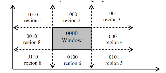
Figure: Positioning of regions surrounding the window

In figure as given above we have noticed that each coding of areas U, D, L and R is done along w.i.t. window region. Since window is neither Left nor Right, neither up nor down so, the respective bits UDLR are 0000; currently see area1 of above figure. The positioning code UDLR is 1010, that is the area1 lying on the position that is upper left side of the window. Hence, area1 has UDLR code 1010 i.e. Up so U=1, not Down so D=0, Left so L=1, not Right so R=0.

The sense of the UDLR code to identify the location of region w.i.t. window is:

1st bit ⇒ Up(U) ; 2nd bit ⇒ Down(D) ;3rd bit ⇒ Left(L) ;  4th bit ⇒ Right(R),

Currently, to perform Line clipping for different line segment that may reside within the window region partially or fully, or may not even lie in the widow area; we utilize the tool of logical ANDing among the UDLR codes of the points lying on the line.

Logical ANDing (^) operation

=>

1 ^ 1 = 1; 1 ^ 0 = 0;

between respective bits implies


Note:


0 ^ 1 = 0; 0 ^ 0 = 0


  • UDLR code of window is 0000 all the time and with respect to this will generate bit codes of other areas.
  • A line segment is observable if both the UDLR codes of the end points of the line segment equal to 0000 that is UDLR code of window area. If the resulting code is not 0000 then, which line segment or section of line segment may or may not be observable

Related Discussions:- Cohen sutherland line clippings algorithm

Is cad only helpful for design drawings, Question: Is CAD only helpful for ...

Question: Is CAD only helpful for design drawings? No. When true-scale, structurally valid drawings are the purpose for CAD's existence; it utilizes is as diverse as imagination

Introduction of visible surface detection, Introduction of Visible Surface ...

Introduction of Visible Surface Detection For displaying a realistic presentation of the given 3Dimentional object, hidden surfaces and hidden lines should be identified fo

Explain three dimensional transformations, Explain Three Dimensional Transf...

Explain Three Dimensional Transformations A 3D geometric transformation is utilized extensively in object modelling and rendering. 2D transformations are naturally extended to

Phong model or phong specular reflection model, Phong Model or Phong Specul...

Phong Model or Phong Specular Reflection Model It is an empirical model that is not based on physics, although physical observation. Phong observed here for extremely shiny su

Types of polygon tables curves and surfaces, Types of Polygon tables curves...

Types of Polygon tables curves and surfaces Attribute tables: This table has object information as transparency, surface reflexivity, texture features of an object in the vi

Axis of rotation - construction of a solid, Axis of Rotation - Construction...

Axis of Rotation - Construction of a solid with a translational sweep Figure:  (a)                                                                          Figure  (b)

Projections - 3d primitive and composite transformations, Projections W...

Projections When all display devices are 2D, you need to devise methods that give a realistic view of a 3D scene onto 2D display. With more and more devices coming in the marke

Design a bitmap for the english vowels, 1. Design a bitmap for the English ...

1. Design a bitmap for the English vowels A, E, I, O, U for two different sizes and then implement the bitmaps to plot these vowels on the display. Keep in mind that baseline of al

Sub classes of orthographic projection, Sub Classes of Orthographic Project...

Sub Classes of Orthographic Projection There are three ordinary sub-classes of Orthographic (axonometric) projections as: 1) Isometric: The direction of projection makes

Write Your Message!

Captcha
Free Assignment Quote

Assured A++ Grade

Get guaranteed satisfaction & time on delivery in every assignment order you paid with us! We ensure premium quality solution document along with free turntin report!

All rights reserved! Copyrights ©2019-2020 ExpertsMind IT Educational Pvt Ltd