Circuits
Typical electronics circuits are created out of a basis set of primitive elements such as capacitors, voltage sources, resistors, transistors and inductors. This set of elements types was selected to be nearly based to primitive principles in our physical understanding of electronic circuits in terms of current, voltage, resistance, and the rate of modification of those values over time. So, when we buy a physical resistor, we go to think only of its resistance; and when we buy a capacitor, we only think of its ability to save charge. But, that physical resistor has some capacitance, and the capacitor has some resistance. Still, it gives us in our designs to have systems that are as close to the perfect models as possible; and it gives that people have been designing with these elements for years, so that we may adopt the strategies that generations of clever people have designed.
The function of combining circuit components is to connect their end terminals with conductors, a phenomena that is usually referred to as wiring. And our function of abstraction is to define the constraints that a circuit components exerts on the voltages and currents of terminals to which the component is connected.
So, armed with the standard basis set of analog circuit element, we may try to create a circuit to control our robot. We have a resistance that change with the light level, but we require a voltage that does so, as well. We may achieve this by using a voltage divider, which is given in diagram. Using an abstract, constraint-based method of the behaviour of circuit elements.
we can calculate the given relationship between Vout and Vin:
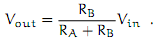
So, if RA = RB, then Vout = Vin/2. Or, in our circuit, if RA actually changes with the amount of light shining on it, then Vout will also modify with the light
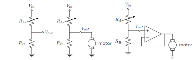
Figure 1.3 Voltage dividers: A. Resistor divider. B. Connected to a motor, in a way that divides the abstraction from part A. C. Connected to a motor, with a buffer.
So, now, we can imagine that we may use this voltage difference that we have build to operate the motor at different velocity, relaying on the light hitting the resistor, using a circuit something like the one given in diagram B. But, sadly, that will not work. It creates out that once we connect the motor to the circuit, it actually modifies the voltages, and we may no longer maintain the voltage difference used to drive the motor.
So, although we have created an abstract design of the behaviour of circuit elements, which lets us analyze the behaviour of a particular complete circuit model, it does not provide us modularity. That is, we cannot prepare two parts of a circuit, understand each of their behaviours, and then obtain the behaviour of the composite machine depend on the behaviour of the separate components. Instead, we could have to reanalyze the joint behaviour of the whole composite system. Lack of modularity creates it very difficult to develop large machine, because two different person, or the same person at two different times, cannot design parts and put them together without understanding the entire.