Change in flux linkage, Electrical Engineering

Assignment Help:

1. The coil remaining stationary with respect to the flux, the flux varies in magnitude with time. Since no motion is involved, no energy conversion takes place. Equation gives the transformer emf (or the pulsational emf ) as in the case of a transformer, in which a time-varying flux linking a stationary coil yields a time-varying voltage.

2. The flux remaining constant, the coil moves through it. A conductor or a coil moving through a magnetic field will have an induced voltage, known as the motional emf (or speed emf ), given by

Motional emf e = BlU

which is often called the cutting-of-flux equation, where B is the flux density of a non- time-varying, uniform magnetic field, l is the length of the conductor, U is the velocity of the conductor, and ¯B, ¯l, and ¯U are mutually perpendicular in their directions. If the motion is rotary in nature, it is also known as rotational voltage. The direction for the motional emf can be worked out from the right-hand rule: if the thumb, first, and second fingers of the right hand are extended so that they are mutually perpendicular to each other, and if the thumb represents the direction of ¯U and the first finger the direction of ¯B, the second finger will then represent the direction of the emf along ¯l.

1425_Change in flux linkage.png

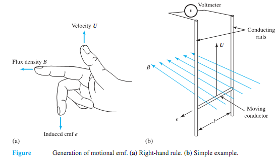
The generation of motional emf is further illustrated by a simple example, where a single-turn coil formed by the moving (or sliding) conductor (moving with velocity U), the two conducting rails, and the voltmeter are situated in a magnetic field of flux density B. The conductor moving with a velocity U, in a direction at right angles to both B and l, sweeps the area lU in 1 second. The flux per unit time in this area is BlU, which is also the flux linkage per unit time with the single-turn coil. Thus, the induced emf e is simply given by BlU. The motional emf (or speed emf) is always associated with the conversion of energy between the mechanical and electrical forms.

3. The coil may move through a time-varying flux; that is to say, both changes (1) and (2) may occur together.Usually one of the two phenomena is so predominant in a given device that the other may be neglected for the purposes of analysis.


Related Discussions:- Change in flux linkage

Explain in detail the operation of 8255 in mode 1, Explain in detail the op...

Explain in detail the operation of 8255 in mode1 taking suitable example. In mode1, Ports A and B are programmed as input or output ports and Port C is used for handshaking.

Digital logic design, how to sort three number in descending order and disp...

how to sort three number in descending order and display on seven segment

Cro, role of trigger circuit in cro

role of trigger circuit in cro

Find the line current after the addition of capacitor bank, Q. Find the lin...

Q. Find the line current after the addition of capacitor bank? A 60-Hz, three-phase motor draws 25 kVA at 0.707 lagging power factor from a 220-V source. It is desired to impro

Discuss the disadvantages of an rc coupled amplifier, Q. Discuss the disadv...

Q. Discuss the disadvantages of an RC coupled amplifier? RC coupled amplifiers have a few disadvantages. The resistors use dc power and so the amplifier has low efficiency. The

Explain electrical contact materials, Explain electrical contact materials....

Explain electrical contact materials. Electrical contact materials: some elements, in their relatively pure forms as copper, nickel, molybdenum, palladium, silver, tungsten and

Explain effect of impurity on conductivity of semiconductor, Explain the ef...

Explain the effect of impurity on the conductivity of a semiconductor. To form a semi-conductor conductive, a small amount of appropriate impurity is added. This is then termed

Show npn common base amplifier, Q. Show NPN Common Base Amplifier? ...

Q. Show NPN Common Base Amplifier? This configuration is used for high frequency applications because the base separates the input and output, minimizing oscillations at h

Active-mode pnp transistors in circuits, Active-mode PNP transistors in cir...

Active-mode PNP transistors in circuits: In the figure, the arrows showing current point in the direction of conventional current - the flow of electrons is in the opposite di

Write Your Message!

Captcha
Free Assignment Quote

Assured A++ Grade

Get guaranteed satisfaction & time on delivery in every assignment order you paid with us! We ensure premium quality solution document along with free turntin report!

All rights reserved! Copyrights ©2019-2020 ExpertsMind IT Educational Pvt Ltd