Can you explain about multiple poles, Electrical Engineering

Assignment Help:

Q. Can you explain about Multiple Poles?

Let us consider that F1(s) has all simple poles except, say, at s = p1 which has a multiplicity m. Then one can write

954_Can you explain about Multiple Poles.png

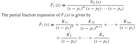
When a multiple root is involved, there will be as many coefficients associated with the multiple root as the order of multiplicity. For each simple pole pk we have just one coefficient Kk, as before.

For simple poles one can proceed as discussed earlier and apply Equation to calculate the residues Kk. To evaluate K11, K12,..., K1m we multiply both sides of Equation by (s - p )m to obtain

24_Can you explain about Multiple Poles1.png

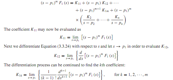
Note that K2,...,Kn terms play no role in determining the coefficients K11,K12,...,K1m because of the multiplying factor (s - p1)m in Equation.

The alternate representation discussed for the case of complex poles may also be extended formultiple poles by combining the terms in Equation corresponding to themultiple root. In an expansion of a quotient of polynomials by partial fractions, it may, in general, be necessary to use a combination of the rules given.


Related Discussions:- Can you explain about multiple poles

What is solar water heating, What do you understand by solar water heating ...

What do you understand by solar water heating and discuss different kind of solar water heating based on collector-storage and circulation type. Discuss integrated collector - s

What are encoder and the decoder, There are zillions of things in electroni...

There are zillions of things in electronics known as encoders. You can look up LCDs and NAND gates as well and this is actual basics.

Determine the flux, Q. Consider themagnetic circuit of Figure. Let the cros...

Q. Consider themagnetic circuit of Figure. Let the cross-sectional area AC of the core, be 16 cm 2 , the average length of the magnetic path in the core lC be 40 cm, the number

Schematic symbols, Schematic Symbols The junction gate field-effect t...

Schematic Symbols The junction gate field-effect transistor or JFET gate is sometimes drawn in the middle of the channel (in place of at the drain or source electrode as in t

Dtl and ttl logic circuits, Q. DTL AND TTL LOGIC CIRCUITs? Bipolar tran...

Q. DTL AND TTL LOGIC CIRCUITs? Bipolar transistorswere the first solid-state switching devices commonly used to implement digital logic circuits in the 1950s and 1960s. These c

Show applications for synchronous motors, Q. Show Applications for Synchron...

Q. Show Applications for Synchronous Motors? With constant-speed operation, power factor control, and high operating efficiency, three-phase synchronous motors are employed in

What is the voltage controlled resistance region, Q. What is the Voltage co...

Q. What is the Voltage controlled resistance region?  In this region the JFET can actually be employed as a variable resistor whose resistance is controlled by the applied gate

Mesh-current equation with controlled sources, Since a controlled source ac...

Since a controlled source acts at its terminals in the same manner as does an independent source, source conversion and application of KCL and KVL relations are treated identically

power system operation, AskWrite short notes on pit head generation. ques...

AskWrite short notes on pit head generation. question #Minimum 100 words accepted#

Boost converter - power supplies , Boost Converter The boost  convert...

Boost Converter The boost  converter has its  output  voltage always  greater than input  voltage like  a buck  converter boost  converter has two  modes.

Write Your Message!

Captcha
Free Assignment Quote

Assured A++ Grade

Get guaranteed satisfaction & time on delivery in every assignment order you paid with us! We ensure premium quality solution document along with free turntin report!

All rights reserved! Copyrights ©2019-2020 ExpertsMind IT Educational Pvt Ltd